Time delay releasing structure for inertia safety mechanism

An inertial and slider technology, applied to aircraft parts, aircraft indicating devices, transportation and packaging, etc., can solve the problems of unusable environment with large vibration, unfavorable product miniaturization design, and low product reliability, so as to achieve enhanced environment The effects of adaptability, improved anti-vibration ability and reliability, and simplified structural design

Active Publication Date: 2017-01-11
GUIZHOU AEROSPACE ELECTRONICS TECH CO LTD
View PDF8 Cites 10 Cited by
  • Summary
  • Abstract
  • Description
  • Claims
  • Application Information

AI Technical Summary

Problems solved by technology

[0004] 1 It cannot be used in an environment with high vibration;
[0005] 2 It cannot be used in products with long delay time and high delay accuracy requirements;
[0006] 3 It is not conducive to product miniaturization design;
[0007] 4 Low product reliability

Method used


Image

  • Time delay releasing structure for inertia safety mechanism
  • Time delay releasing structure for inertia safety mechanism
  • Time delay releasing structure for inertia safety mechanism

Examples


Embodiment Construction

[0019] The technical solutions of the present invention are further described below, but the claimed scope is not limited to the description.

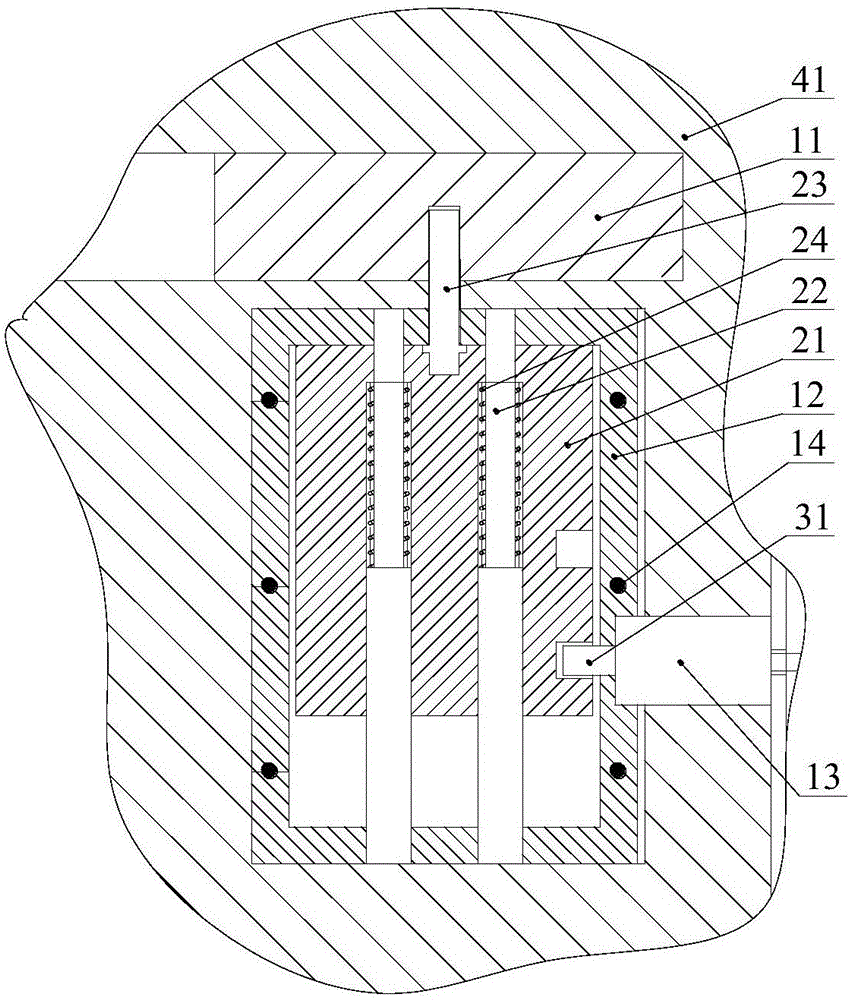
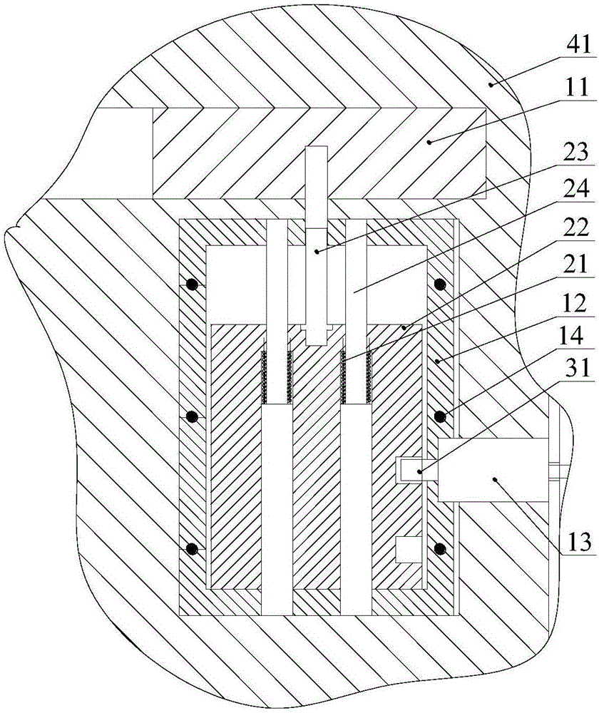
[0020] like figure 1 , figure 2 The illustrated inertial safety mechanism delay release structure includes an isolation slider 11, a fixed frame 12, an electromagnetic pin puller 13, an inertial slider 21, a guide shaft 22, a slider end pin 23, and a compression spring 24; the The isolation slider 11 is laterally arranged on the base 41, and there is a blind hole at the bottom of the isolation slider 11; the fixing frame 12 is fixed on the base 41 at a position below the isolation slider 11, and a slidable inertial slider is arranged in the fixing frame 12 21. A guide shaft 22 is fixed in the inertia slider 21, a compression spring 24 is sleeved on the guide shaft 22, a slider end pin 23 is fixed in the middle of the top of the inertia slider 21, and the upper end of the slider end pin 23 can be inserted into the isolation slider 11...


PUM


Abstract

The invention provides a time delay releasing structure for an inertia safety mechanism. The time delay releasing structure for the inertia safety mechanism comprises an isolation slider, a fixing frame, an electromagnetic pin puller, an inertial slider, a guide shaft, a slider end pin, and a compression spring; the isolation slider is transversely arranged on the base, and the bottom of the isolation slider is provided with a blind hole; the fixing frame is fixed on the base and at the lower position of the isolation slider, a slidable inertial slider is arranged within the fixing frame, the guide shaft is fixed within the inertial slider, and the compression spring is arranged on the guide shaft in a sleeved mode; the slider end pin is fixed on the middle of the top of the inertial slider, and the upper end of the slider end pin is arranged in the inside of the middle section of the isolation slider in a inserted mode; the side of the fixing frame is provided with the electromagnetic pin puller arranged on the base. According to the time delay releasing structure for inertia safety mechanism, the structure design of inertia safety mechanism is simplified, the delay time of the inertia safety mechanism can be decided at will, the delay precision of the inertia safety mechanism is improved, the anti vibration ability and reliability of the inertia safety mechanism are improved, the adaptive capacity to environment of the inertia safety mechanism is increased, and the time delay releasing structure is beneficial for the miniaturization development of the inertia safety mechanism.

Description

technical field [0001] The invention relates to a delay release structure of an inertial insurance mechanism. Background technique [0002] The inertial insurance mechanism is an important part of the safety component starter, safety component actuator and other components in the aircraft. Its function is to sense the flight overload of the aircraft and release the inertial insurance release for the safety component starter or safety component actuator. In the design of aircraft, the inertial safety mechanism is often required to have a time-delay function. The traditional design method is to add a clock mechanism to the slider in the inertial mechanism and extend the stroke of the inertial slider to delay the release time of the inertial safety mechanism, but the clock mechanism The gear and rack are meshed together, and the clock mechanism and the inertia slider are also matched with the rack and pinion. When the aircraft is subjected to large vibration during service proc...

Claims


Application Information

Patent Timeline
Patent Type & Authority Applications(China)
IPC IPC(8): B64D45/00
CPCB64D45/00
Inventor 石云陆
Owner GUIZHOU AEROSPACE ELECTRONICS TECH CO LTD
Why Eureka
Try Eureka