Gravitational settling type gas-liquid separation method

A technology of gas-liquid separation and gravity sedimentation, which is applied in the direction of separation methods, dispersed particle separation, chemical instruments and methods, etc., can solve the problems of low gas-liquid separation efficiency and low cost, and achieve high-efficiency gas-liquid separation capabilities and manufacturing costs Low, simple structure effect

Inactive Publication Date: 2017-01-11
CHENGDU ZHENGSHENG ENERGY TECH DEV CO LTD
View PDF5 Cites 4 Cited by
  • Summary
  • Abstract
  • Description
  • Claims
  • Application Information

AI Technical Summary

Problems solved by technology

[0003] The purpose of the present invention is to overcome the deficiencies of the prior art, to provide a gravity sedimentation gas-liquid separation method, which has higher gas-liquid separation speed and separation efficiency, and is simple in structure and lower in cost, which solves the problems in the prior art. Technical problem of low gas-liquid separation efficiency

Method used


Image

  • Gravitational settling type gas-liquid separation method
  • Gravitational settling type gas-liquid separation method

Examples


Embodiment 1

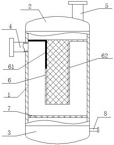
[0024] Gravity sedimentation gas-liquid separation method, such as figure 1 and figure 2 shown, including steps:

[0025] Step 1) By installing an upper end cap 2 on the upper end of the cylinder body 1 and a lower end cap 3 on the lower end of the cylinder body 1, the gas-liquid mixture enters the separator from the inlet pipe 4 provided on the cylinder wall near the upper end of the cylinder body 1.

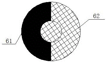
[0026] Step 2) A filter element 6 is provided in the cylinder body 1, the filter element 6 includes a flow guide part 61 and a filter part 62, the flow guide part 61 is made of an air-tight material, and the flow guide part 61 is located near the filter element 6 One side of the inlet pipe 4, after the gas is filtered, is discharged through the outlet pipe 5 provided on the upper end cover 2.

[0027] Step 3) The separated liquid is discharged through a drain pipe 8 arranged at the lowest point of the bottom surface of the lower end cover 3 .

[0028] In oil exploitation, t...

Embodiment 2

[0030] This embodiment is a further improvement on the above-mentioned embodiment, as figure 1 and figure 2 As shown, in this embodiment, the section of the filter element 6 is T-shaped, the horizontal part of the filter element 6 is detachably connected to the inner wall of the cylinder 1, and the upper half of the horizontal part and the vertical part of the filter element 6 near the side of the intake pipe 4 The section constitutes a diversion part 61, and the filter element 6 with a T-shaped cross section is convenient for installation and fixing in the cylinder body 1, and can facilitate the flow of the gas-liquid mixture. The bottom of the filter element 6 in the cylinder body 1 is detachably provided with a filter screen 7, which is used to filter impurities in the gas-liquid mixture, so as to facilitate further processing of the liquid part in the gas-liquid mixture. The filter screen 7 and the inner wall of the cylinder body 1 can be separated. The connection is dis...

Embodiment 3

[0032] This embodiment is a further improvement on the above-mentioned embodiment, as figure 1 and figure 2 As shown, in this embodiment, the upper end cap 2 and the lower end cap 3 are threadedly connected with the cylinder body 1, the connection between the upper end cap 2 and the lower end cap 3 and the cylinder body 1 is coated with sealant, and the air inlet pipe 4 is tightly connected with the cylinder body 1 , the air outlet pipe 5 is in sealing connection with the upper end cover 2, and the liquid discharge pipe 8 is in sealing connection with the lower end cover 3. The upper end cover 2 and the lower end cover 3 are threadedly connected, which is convenient for the maintenance of the present invention, and the above-mentioned connection nodes are sealed to ensure the airtightness of the present invention.


PUM


Abstract

The invention discloses a gravitational settling type gas-liquid separation method. The gravitational settling gas-liquid separation method comprises the following steps of: step (1) arranging an upper end cover at the upper end of a barrel, arranging a lower end cover at the lower end of the barrel, and arranging a gas inlet pipe on the barrel wall close to the upper end to cause a gas-liquid mixture to enter a separator from the barrel; step (2) arranging a filter element in the barrel, wherein the filter element comprises a diversion part and a filtration part, the diversion part is made from an airtight material and is located at one side, close to the air inlet pipe, of the filter element, and discharging gas through a gas outlet pipe arranged on the upper end cover after filtering the gas; and step (3) discharging liquid obtained after separation by arranging a liquid draining pipe at the lowest point of the bottom surface of the lower end cover.

Description

technical field [0001] The invention relates to the technical field of oil and gas exploitation equipment, in particular to a gravity-settling gas-liquid separation method. Background technique [0002] In the process of oilfield exploitation, abnormal low pressure occurred in some oilfields, which brought certain difficulties to well workover. Some gas wells were exploited at low pressure, and sand was buried in the strata, which could not be cleaned up in time, which reduced the production of gas wells or even stopped production. When downhole operations are carried out without external energy supplementation, the workover fluid pollutes the formation more and more seriously, which makes the drainage period after the action continue to prolong. Therefore, it is necessary to pressurize this type of gas wells no matter during production or liquid drainage. In the prior art, the Gasjack unit can carry out gas-water mixed transmission, that is, the unit has its own separation...

Claims


Application Information

Patent Timeline
Patent Type & Authority Applications(China)
IPC IPC(8): C10L3/10B01D50/00
CPCC10L3/101C10L2290/547B01D50/20
Inventor 黄建军
Owner CHENGDU ZHENGSHENG ENERGY TECH DEV CO LTD
Why Eureka
Try Eureka