Dye vat water circulation system
A technology of water circulation and dyeing vat, which is applied in the direction of processing textile materials equipment configuration, etc., can solve problems such as poor effect, severe vibration of pipelines, equipment impact, etc., and achieve the effects of reducing waste, improving automation, and saving energy
- Summary
- Abstract
- Description
- Claims
- Application Information
AI Technical Summary
Problems solved by technology
Method used
Image

Examples
Embodiment Construction
[0027] Figure 1~3 It is the best embodiment of the present invention, below in conjunction with attached Figure 1~3 The present invention will be further described.
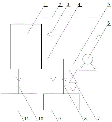
[0028] Such as figure 1 As shown, a water circulation system for a dyeing vat includes a dyeing vat 1 , a recycling pool 9 and a waste water pool 11 . The top of the dyeing vat 1 is provided with a dyeing vat water injection pipe 2 for injecting water into the dyeing vat 1 , and the bottom of the dyeing vat 1 is provided with a dyeing vat drainage pipe 10 for draining, and the dyeing vat drainage pipe 10 is connected to the waste water pool 11 .
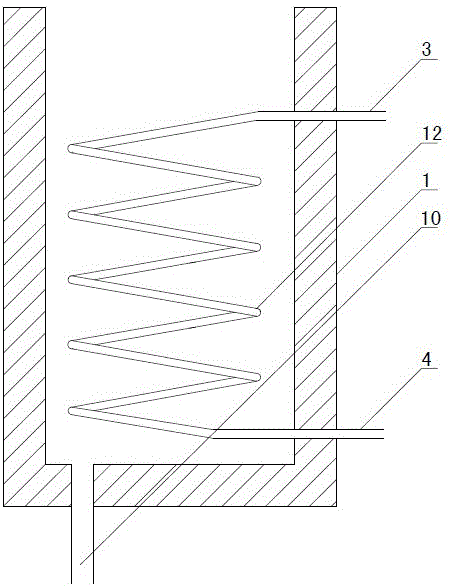
[0029] Such as figure 2 As shown, a threaded heat exchange tube 12 is provided in the dye vat 1, and the inlet and outlet of the threaded heat exchange tube 12 are respectively connected to one end of the heat exchange water injection pipe 3 and one end of the heat exchange water outlet pipe 4, and the other end of the heat exchange water injection pipe 3 passes t...
PUM
 Abstract
Description
Claims
Application Information
PatSnap Eureka turns technology decisions into work you can execute. Powered by our Innovation Knowledge Graph, it runs expert workflows across engineering, life sciences, materials and intellectual property. Get your review-ready output in minutes.


