Beam column connection piece

A technology of beam-column connection and connection part, which is applied in the field of connection parts, can solve the problems of inability to realize large-scale standardized production, reduce installation efficiency, and increase installation difficulty, so as to improve installation efficiency, anti-seismic function, utilization rate and aesthetics , reducing the effect of the connection link

Inactive Publication Date: 2017-01-11
陈贵荣
View PDF5 Cites 12 Cited by
  • Summary
  • Abstract
  • Description
  • Claims
  • Application Information

AI Technical Summary

Problems solved by technology

Second, there are many bolts and other fastening connections or welding connections on site, which will increase the difficulty of installation, reduce installation efficiency, and result in high labor and time costs for on-site construction.
The third is that the traditional building steel structure frame beams and columns or beams and beams are connected by bolt fastening or welding, and the respective connection ends must be designed and processed for matching connections. When standard profiles are used for beams or columns , the connecting ends must be designed and processed separately. When beams or columns do not use standard profiles, they need to be specially manufactured. Both methods cannot achieve mass standardized production. The cost is high, and beams or columns are prone to dimensional processing errors. The connection error makes it difficult for the fragile connection position to bear the weight of the building and the transmission of the load force to support the weight of the object above it
However, although this structure has effectively improved the connection between beams and columns, its structure is complicated and processing is troublesome. Its specification is not a common connection interface in the existing construction field. The patent applicant has researched and developed a beam-to-column connector that can be applied to conventional specifications and can be mass-produced

Method used


Image

  • Beam column connection piece
  • Beam column connection piece
  • Beam column connection piece

Examples


Embodiment Construction

[0023] Specific embodiments of the present invention will be described in detail below in conjunction with the accompanying drawings.

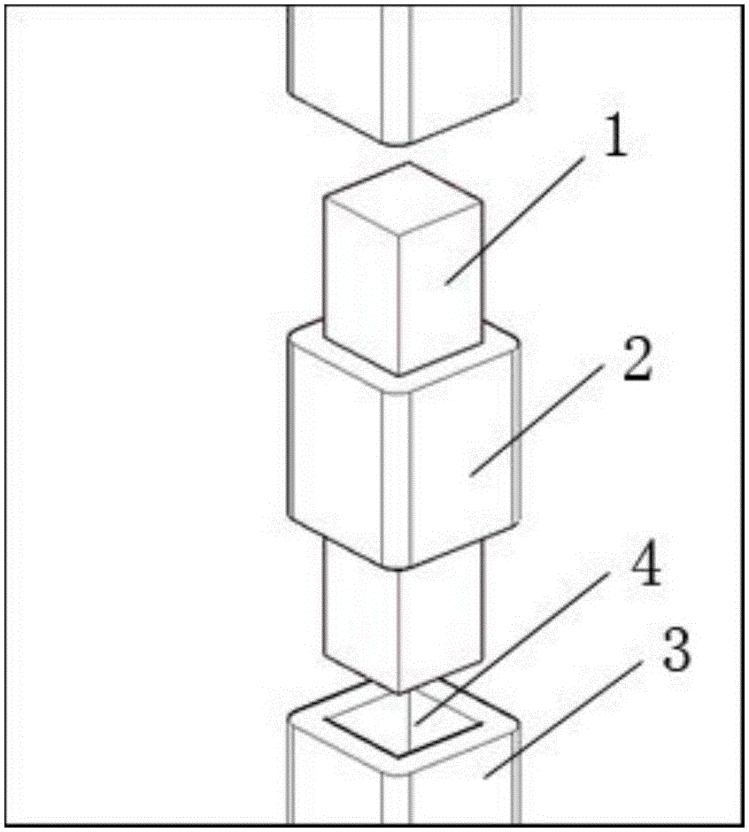
[0024] Such as figure 1 As shown, the present invention includes a connection body 2, the upper and lower ends of the connection body 2 extend a square column connection part 1, the center of the column connection part 1 coincides with the center of the end face of the connection body 2, and the end of the column 3 is concave A column connection part installation groove 4 is formed to cooperate with the column connection part 1. The upper and lower ends of the column connection part 1 are respectively connected to the column 3 through the column connection part installation groove 4. The cross-section shape of the connecting body 2 is the same as that of the column 3.

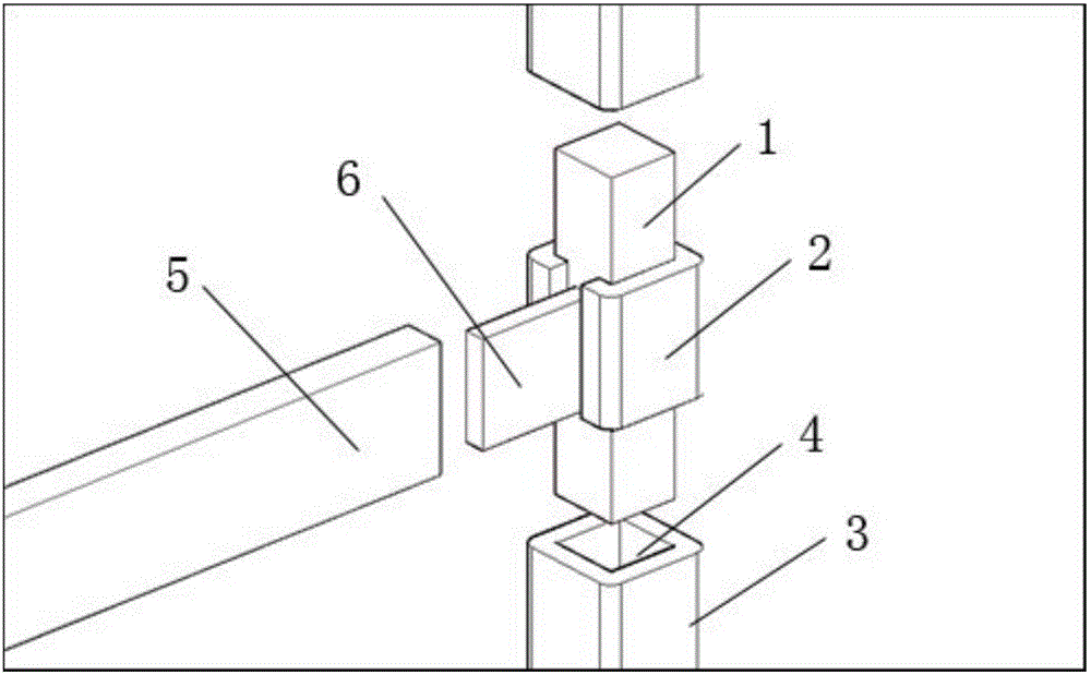
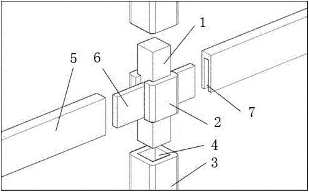
[0025] Furthermore, in the middle of the side of the connecting body 2 is provided with at least one beam connecting portion 6 that hangs outwards in a square shape. The verti...


PUM


Abstract

The invention provides a beam column connection piece, and belongs to the technical field of connection members between beams and columns in buildings. The beam column connection piece includes a connection body; a square-shaped column connection portion extends out from the upper end and the lower end of the connection body; the center of the column connection portion coincides with the center of an end surface of the connection body; ends of a column recess inward to form column connection portion installation grooves matching the column connection portion; the upper end and the lower end of the column connection portion are connected to the column through the column connection portion installation grooves; and the shape of a cross section of the square-shaped connection body is identical to the shape of the cross section of the column. The beam column connection piece is simple in structure; the column connection portion and beam connection portions are arranged on the connection body, and then a suitable type of column connection piece can be selected to construct; and the use of the beam column connection piece is standardized, and the common standard of beams and columns can be fixed in our life, and mass production of the beams and the columns can be achieved.

Description

technical field [0001] The invention belongs to the technical field of connecting parts between beams and columns in buildings, and in particular relates to a beam-column connecting piece. Background technique [0002] A beam is a large number of bent rods in machinery, construction and other projects, such as crane girders, train wheel axles, etc. In a broad sense, this general external force is mainly lateral force, and the deformation of rods is mainly bending The main deformed members are called beams; columns are building middle vertical main structural parts. The beam and column of the existing building steel structure frame or the beam and the beam are directly connected by fasteners such as bolts or through welding, etc., the force is poor, the connection is fragile, and the gravity of the beam, column, floor, etc. is finally transmitted to the connection. The joints are borne by connecting fasteners or welded parts, which will cause excessive stress concentratio...

Claims


Application Information

Patent Timeline
Patent Type & Authority Applications(China)
IPC IPC(8): E04B1/58
Inventor 陈贵荣
Owner 陈贵荣
Why Eureka
Try Eureka