Supporting seat
A technology of supporting seat and adjusting device, which is applied to supporting machines, special foundation arrangements, engine frames, etc., can solve the problems of time-consuming and laborious operation, low work efficiency, and damage to rotating machinery.
- Summary
- Abstract
- Description
- Claims
- Application Information
AI Technical Summary
Problems solved by technology
Method used
Image
Examples
Embodiment 1
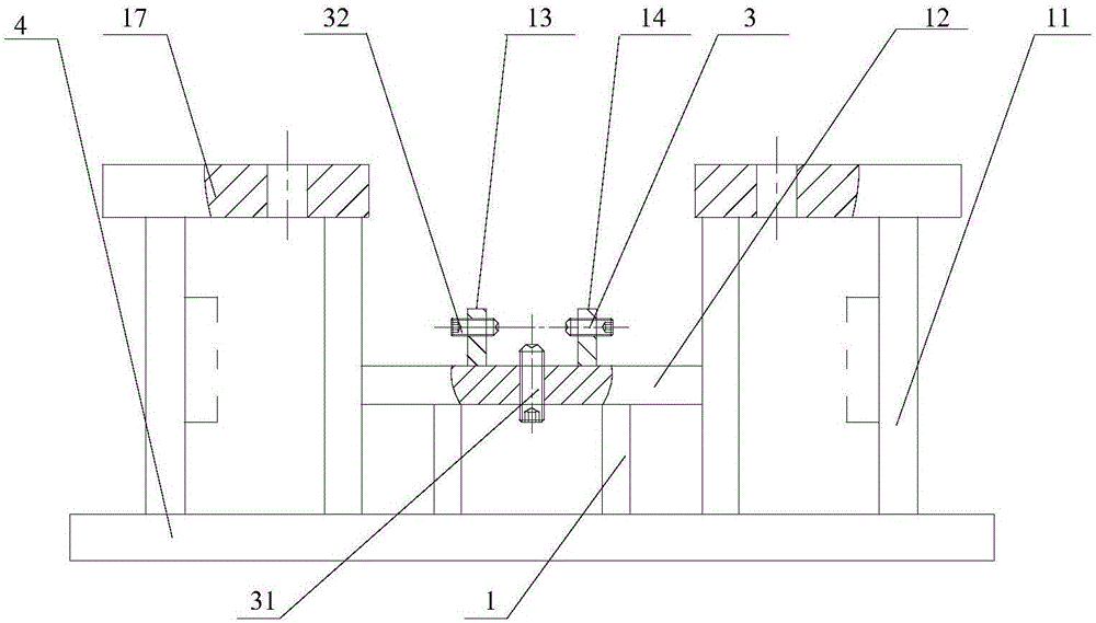
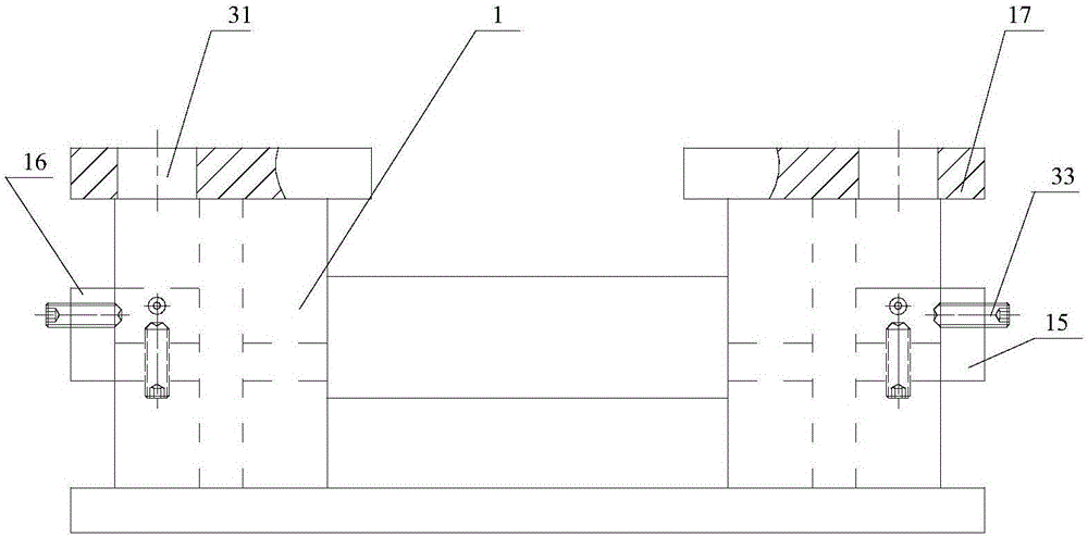
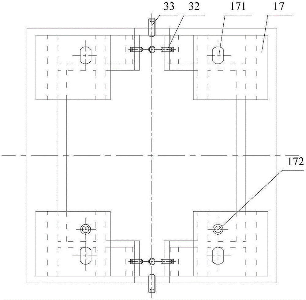
[0038] see Figure 1-4 , the present invention discloses a support seat, wherein the support seat includes a support seat body 1 , a housing 2 and an adjustment device 3 . Wherein, the housing 2 is used to contain the rotating machine to be installed, and the housing 2 is arranged on the support base body 1. The setting here may mean that the housing 2 is only placed on the support base body 1, and it is connected with the support base body 1. Without any connection relationship, it can also mean that the housing 2 is placed on the support base body 1 first, and the housing 2 can be fixed on the support base body 1 after the adjusting device 3 is adjusted. It can be understood that since the rotating machines to be installed can have various shapes, in order to realize the housing of various rotating machines in the housing 2, the housing 2 can be a housing with a circular, square or polygonal cross section. 2. The adjustment device 3 is installed on the support base body 1 ...
Embodiment 2
[0042] In yet another embodiment provided by the present invention, the structure of the supporting seat in this embodiment is similar to that in the first embodiment, so the similarities will not be repeated, and only the differences will be introduced.
[0043] In this embodiment, it is specifically disclosed that the adjustment device 3 includes a first adjustment device 31 , a second adjustment device 32 and a third adjustment device 33 . Among them, the first adjustment device 31 is installed on the bottom of the support base body 1 for adjusting the displacement of the housing 2 in the up and down direction; the second adjustment device 32 is installed on the left and right sides of the support base body 1 for adjusting the displacement of the housing 2. 2 displacement in the left and right direction; the third adjustment device 33 is installed on the front and rear sides of the support seat body 1 for adjusting the displacement of the housing 2 in the front and rear dire...
Embodiment 3
[0056] In the third embodiment provided by the present invention, the supporting seat in this embodiment is similar in structure to the supporting seat in the second embodiment, so the similarities will not be repeated, and only the differences will be introduced.
[0057] In this embodiment, it is specifically disclosed that the adjusting device 3 is an air cylinder or a hydraulic cylinder, that is, the first adjusting device 31 , the second adjusting device 32 and the third adjusting device 33 are all air cylinders or hydraulic cylinders. The movement of the casing 2 is achieved by driving the cylinder or the hydraulic cylinder, and then the position alignment and adjustment of the rotary machine located in the casing 2 is realized.
[0058] It should be noted that some of the first adjusting device 31 , the second adjusting device 32 and the third adjusting device 33 can also be arbitrarily set to be air cylinders or hydraulic cylinders, and some to be adjusting screws. The...
PUM
 Abstract
Description
Claims
Application Information
 - R&D
- Intellectual Property
- Life Sciences
- Materials
- Tech Scout
- Unparalleled Data Quality
- Higher Quality Content
- 60% Fewer Hallucinations
Browse by: Latest US Patents, China's latest patents, Technical Efficacy Thesaurus, Application Domain, Technology Topic, Popular Technical Reports.
© 2025 PatSnap. All rights reserved.Legal|Privacy policy|Modern Slavery Act Transparency Statement|Sitemap|About US| Contact US: help@patsnap.com


