Tube-on-sheet heat exchanger type water heater

A technology of heat exchangers and water heaters, applied in water heaters, fluid heaters, lighting and heating equipment, etc., can solve problems such as hair, hair cream, dirt clogging and deposition, failure to meet the needs of use, and high cleaning frequency. To achieve the effect of resource saving, flexible use and smooth flow

Inactive Publication Date: 2017-01-11
东莞市康源节能科技有限公司
View PDF1 Cites 0 Cited by
  • Summary
  • Abstract
  • Description
  • Claims
  • Application Information

AI Technical Summary

Problems solved by technology

The serpentine heat exchange tube needs support, and the support of the serpentine heat exchange tube and the serpentine heat exchange tube itself become obstacles in the sewage flow channel of the heat exchanger, which is particularly easy to cause hair, hair cream, and dirt blockage and deposition, and the cleaning frequency is high. Cleaning is also more troublesome, and the defects are very obvious, which cannot meet the needs of use

Method used


Image

  • Tube-on-sheet heat exchanger type water heater
  • Tube-on-sheet heat exchanger type water heater
  • Tube-on-sheet heat exchanger type water heater

Examples


Embodiment 1

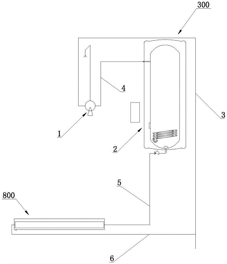
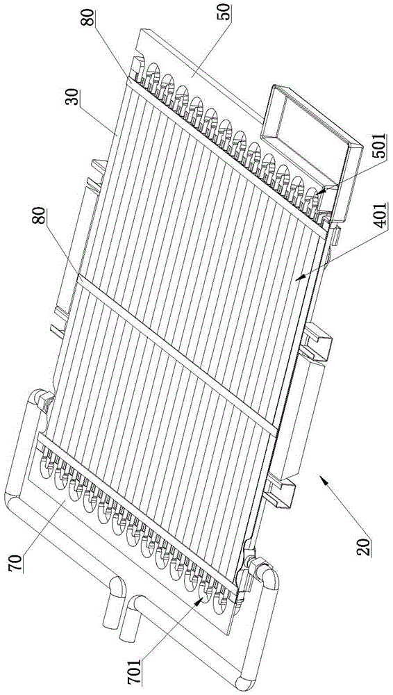
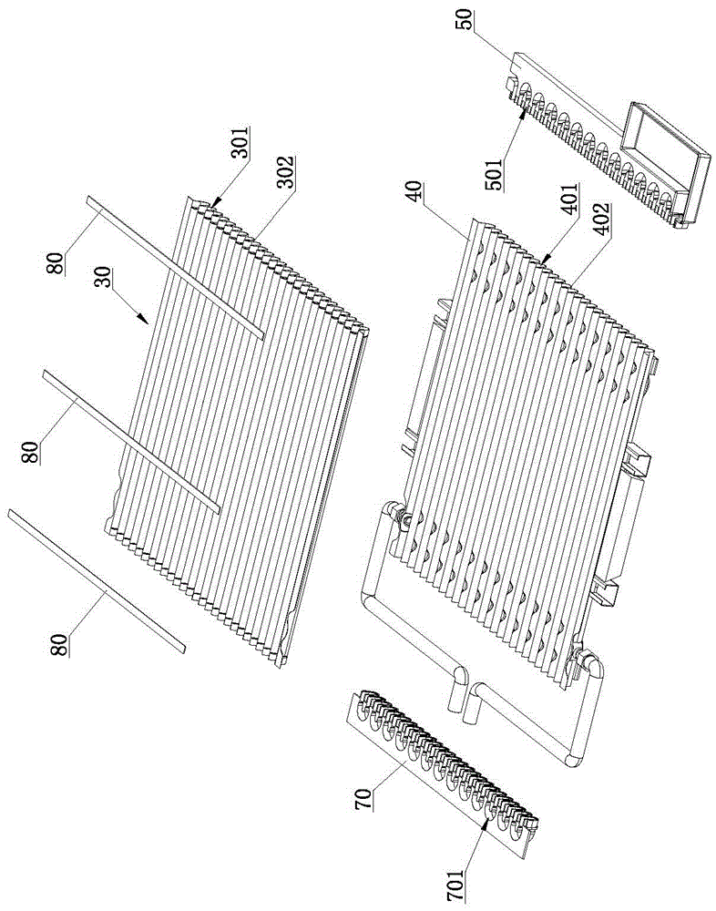
[0043] Such as Figure 1 to Figure 9 As shown, a plate and tube heat exchanger type water heater includes a water heater 300, which is characterized in that it also includes a plate and tube heat exchanger 800, a heat exchange outlet pipe 5 and a heat exchange inlet pipe 6; the plate and tube heat exchanger 800 Including core body 20, core body 20 includes A plate 30, B plate 40, front sealing plate 50 and rear sealing plate 70; Sinking groove protrusion 302; B plate 40 is provided with B plate sinking groove 401 corresponding to A plate sinking groove 301, the back of B plate sinking groove 401 is B plate sinking groove protrusion 402, two adjacent B plate sinking grooves 401 is connected; A board sinker protrusion 302 is set in B board sinker 401 and there is a gap between A board sinker protrusion 302 and B board sinker 401, A board sinker protrusion 302 and B board sinker Both ends of 401 are provided with the structure of the sealing gap, so that the medium flow channel ...

Embodiment 2

[0072] Such as Figure 10 to Figure 12 As shown, the difference between the second embodiment and the first embodiment is that the plate and tube heat exchanger 800 also includes a cover plate 10 covering the A plate 30, the cover plate 10 is provided with a water leakage hole 101, and the water leakage hole 101 A filter screen 102 is provided at the place, and the front sealing plate 50 is provided with a sump 503 for collecting the fluid flowing out of the leakage hole 101. The sump 503 communicates with the A plate sink 301, and the leakage hole 101 is connected with the shampoo bed body. The waste water outlet of 1 is connected.

[0073] In this embodiment, a cover plate 10 is added, and the cover plate 10 covers the plate A 30 so as to seal the sinker groove 301 of the plate A. In actual application, the cover plate 10 may or may not be in contact with the protrusion on the top surface of the A plate 30 . The waste water of shampoo bed body 1 flows in from leaking hole ...

Embodiment 3

[0076] Such as Figure 13 to Figure 15 As shown, the difference between the third embodiment and the second embodiment is that the plate and tube heat exchanger 800 further includes a box body 100 , and the core body 20 is installed in the box body 100 . In actual application, when the core body 20 is installed in the box body 100, the bottom surface of the box body 100 can abut against the protrusion 402 of the sinking groove of the plate B, so that the fluid in the fluid area surrounded by the box body 100 and the sinking groove protrusion 402 of the plate B flow in tank 200, as Figure 13shown. The bottom surface of the box body 100 may not abut against the B-board sinker protrusion 402 , so that the fluid flows between the B-board 40 and the box body 100 . On the basis of the above-mentioned embodiment 2, the tank 100 is added to introduce waste water into the fluid tank 200, so that the tap water in the medium flow channel 60 absorbs the heat of the waste water in the f...


PUM


Abstract

The invention relates to the technical field of water heaters, in particular to a tube-on-sheet heat exchanger type water heater. The tube-on-sheet heat exchanger type water heater comprises a water heater body and further comprises a tube-on-sheet heat exchanger, a heat exchange water outlet pipe and a heat exchange water inlet pipe. The tube-on-sheet heat exchanger comprises a core body, wherein the core body comprises a plate A, a plate B, a front sealing plate and a rear sealing plate. The tube-on-sheet heat exchanger type water heater recovers the heat of waste water, the energy consumption caused by tap water heating is reduced, resources are saved, and the usage cost is reduced. The tube-on-sheet heat exchanger adopts a plate A sinking tank formed in the plate A and a plate B sinking tank formed in the plate B, and the heat exchange coefficient is higher after heat exchange of the plate A and the plate B is strengthened by adopting sheets and corrugations. The plate A and the plate B are combined to form the core body by adopting sheet pipe structures, the overall smoothness of the plate A sinking tank is good, waste water is smooth to flow, and the problem of remarkable reduction of the heat transfer coefficient due to dirt blockage and sedimentation is effectively avoided. In addition, tap water is good in heat absorption effect in a medium channel, and the waste water and tap water heat exchange effect is good.

Description

technical field [0001] The invention relates to the technical field of water heaters, in particular to a plate-tube heat exchanger type water heater. Background technique [0002] The recovery and reuse of low-grade waste fluid energy has always been a research focus in the field of energy conservation. The biggest problem in the energy recovery of low-grade waste fluids is fouling, deposition and the significant reduction in heat transfer coefficient caused by them. For large-scale sewage systems, this problem can be solved through filtration and other treatment methods. For small and medium-sized sewage systems such as showers, it is uneconomical to use filtration and other treatment methods, and the heat loss in the treatment process is large, and heat recovery may even be impossible or lost. economic significance. [0003] At present, there are also some water heaters that use waste heat recovery devices to recover the residual temperature of sewage, but due to the lim...

Claims


Application Information

Patent Timeline
Patent Type & Authority Applications(China)
IPC IPC(8): F24H1/00F24H9/00F24H9/18
CPCF24H1/00F24H9/0005F24H9/1809
Inventor 张加振
Owner 东莞市康源节能科技有限公司
Why Eureka
Try Eureka