Pressure cell fast positioning and fixing device

A technology of fixing devices and pressure boxes, which is applied to measuring devices, force/torque/work measuring instruments, instruments, etc., can solve problems such as high requirements for workers, complicated procedures, poor shock resistance, etc., and achieve fast and flexible operation and environmental protection Adaptable and well-structured effects

Inactive Publication Date: 2017-01-11
INST OF ROCK AND SOIL MECHANICS - CHINESE ACAD OF SCI
View PDF9 Cites 9 Cited by
  • Summary
  • Abstract
  • Description
  • Claims
  • Application Information

AI Technical Summary

Problems solved by technology

Although this type of method has the advantage of simple operation, there are still certain problems: that is, this type of device lacks a height adjustment mechanism. The lack of a suitable force location makes it impossible to bury, resulting in the failure of the monitoring task. At the same time, because the fixed iron wire itself and the bolt have a certain thickness, when it covers the surface of the pressure cell, the pressure cell and the measured object will change from the original complete "surface- Surface" contact becomes partial "surface-surface" contact, which has a certain impact on the measurement results of the pressure cell (Chinese utility model patent application number 201220698095.5, the patent name is "pressure cell fixing device", the application case The pressure cell The "iron wire + bolt + box groove" mode adopted has a delay in measurement time and measurement errors; the Chinese utility model patent application number 201320269570.1, the patent name is "soil pressure box fixing device", which provides a "iron wire + tray" "Bundling, and then welding the whole pallet to the immovable body to fix the pressure box, but the process is complicated, the requirements for the staff themselves are high, and there is no effective protection device for the pressure b

Method used


Image

  • Pressure cell fast positioning and fixing device

Examples


Embodiment Construction

[0013] The present invention will be described in further detail below in conjunction with the accompanying drawings.

[0014] see Attachment.

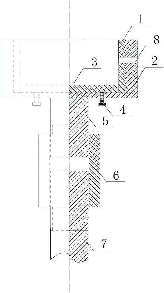
[0015] A fast positioning and fixing device for a pressure box, the fixing device is composed of a bearing base and a lifting bracket, the bearing base 2 is in the shape of a semi-closed hollow cylinder, and the inner wall of the bearing base 2 is fixedly embedded with a rubber buffer layer 1, The pressure box can be double protected by the bearing base 2 and the rubber buffer layer 1, so that it is free from the impact damage caused by shotcrete during the initial support. In addition, the bearing base 2 and the rubber buffer layer 1 are fixed. The size of the cavity should be slightly larger than the size of the pressure box. The fine-tuning plate 3 is movable in the abdominal cavity of the bearing base 2. Four fine-tuning bolts 4 are arranged symmetrically on the bottom of the bearing base 2. The upper ends of the fine-tuning bolts...


PUM


Abstract

The present invention relates to a pressure cell fixing device. The pressure cell fixing device is composed of a carrying base and a lifting bracket; the carrying base is semi-closed hollow cylinder-shaped; a fine adjustment plate is movably arranged in the cavity of the carrying base; the bottom of the carrying base is symmetrically provided with four fine adjustment bolts; the upper end heads of the fine adjustment bolts are matched with the bottom of the fine adjustment plate; the lifting bracket is composed of an upper spiral bracket, a lower spiral bracket and a rotating handle; the upper end head of the upper spiral bracket is fixedly connected with the bottom of the carrying base; the device can rise and descend rapidly by adjusting the rotating handle; and the complete attachment of a pressure cell to the surface of surrounding rock can be realized by means of the fine adjustment bolts, an optimal contact effect can be achieved, and accurate measurement can be realized. The pressure cell fast positioning and fixing device of the invention has the advantages of reasonable structure, simple installation, high environmental adaptability and fast and flexible operation, and is especially suitable for the fast positioning and fixing of a pressure cell between tunnel surrounding rock and a steel arch support structure in underground construction.

Description

technical field [0001] The invention relates to a pressure box fixing device, in particular to a pressure box fast positioning and fixing device used between tunnel surrounding rock and steel arch support structure in underground engineering. Background technique [0002] At present, in the process of remote monitoring of many mountain tunnels in my country, in order to obtain the initial detailed vault pressure value and its change law in real time, grasp the relaxation and change characteristics of the surrounding rock, so as to quickly predict the appropriate supporting time for the surrounding rock, To achieve the best support effect, on-site monitoring personnel widely use pressure cells, which are effective and powerful smart sensors. However, due to the unevenness of the surrounding rock surface of the vault and the frequent occurrence of over-excavation phenomena in mountain tunnels after construction blasting, it is difficult for field workers to find A suitable pre...

Claims


Application Information

Patent Timeline
IPC IPC(8): G01L5/00
CPCG01L5/00
Inventor 江权冉曙光宋磊博林恩德王百林程涛刘挺吕勇刚
Owner INST OF ROCK AND SOIL MECHANICS - CHINESE ACAD OF SCI
Why Eureka
Try Eureka