Eureka AIR delivers breakthrough ideas for toughest innovation challenges, trusted by R&D personnel around the world.

Networked radiation environment monitoring system

An environmental monitoring system and environmental monitoring technology, applied in the field of networked radiation environmental monitoring system, can solve problems such as failure, loud noise, and loss of contact between the monitoring system and the headquarters

Inactive Publication Date: 2017-01-11
EAST CHINA UNIV OF TECH
View PDF2 Cites 4 Cited by
  • Summary
  • Abstract
  • Description
  • Claims
  • Application Information

AI Technical Summary

Problems solved by technology

In the process of use, it was found that due to design defects, the old system mainly had the following problems: the generator was started slowly by manpower, and the noise was loud, the system equipment was unstable, and failures occurred frequently, and the system availability was low
In particular, the monitoring system has no automatic continuous monitoring and real-time data transmission functions, and can only rely on manual positioning monitoring and manual reporting of monitoring data, which has low work efficiency
The single voice communication method makes it impossible for the monitoring system to report data to the command center after entering the "blind zone", and the monitoring system completely loses contact with the command center
Due to the absence of an environmental radiation monitoring system and monitoring software, online, real-time, and automatic monitoring and alarming of environmental radiation conditions cannot be realized. In an accident state, it is difficult for the monitoring command center to obtain the data of the monitoring system in time, and it is impossible to summarize and analyze the relevant data. , affecting the guidance work of the command center

Method used


Image

  • Networked radiation environment monitoring system

Examples


Embodiment Construction

[0061] In order to make the objectives, technical solutions and advantages of the present invention clearer, the present invention will be further described in detail below in conjunction with embodiments. It should be understood that the specific embodiments described herein are only used to explain the present invention, but not to limit the present invention.

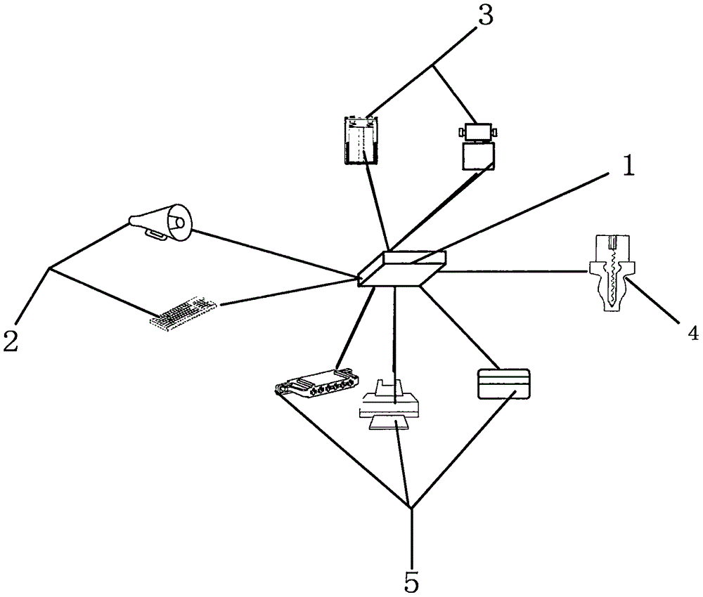
[0062] Attached below figure 1 The application principle of the present invention will be further described. The networked radiation environment monitoring system includes: 1. a data processing host; 2. a power supply system; 3. a radiation environment monitoring device; 4. an alarm indication module; 5. a real-time signal transmission system;

[0063] The radiation environment monitoring device 3 and the power supply system 2 are connected to the data processing host 1 through the real-time signal transmission system 5, and the alarm indication module 4 is an alarm signal output device, which is connected to the data pr...


PUM


Abstract

The present invention discloses a networked radiation environment monitoring system. A radiation environment monitoring device and a power supply system are connected with a data processing host through a real-time signal transmission system. An alarm indication module is an alarm signal output device and is connected with the data processing host. According to the technical scheme of the invention, the on-line, real-time, automatic monitoring and alarming advantages are realized. By means of the system, the screening of an oracle database is realized efficiently based on the data redundancy method. Through checking data and verifying existing data, necessary data are queried and verified, so that the accuracy and the uniqueness of supplied data are realized. Meanwhile, the data redundant condition is avoided. The system has the redundant data recording function, so that the integrity and the accuracy of the equipment supply manufacturer information in an electric energy replacement module are improved. The redundancy problem of the data information is effectively solved. Moreover, the system improves the working efficiency of the subsequent operation.

Description

Technical field [0001] The invention belongs to the technical field of environmental monitoring, and particularly relates to a networked radiation environment monitoring system. Background technique [0002] With the continuous improvement of environmental quality requirements and increasing attention to radiation protection, the real-time monitoring technology of radiation levels in nuclear facilities and the surrounding environment will continue to be studied and improved as an important aspect, and will follow in other fields. Further development with the development of science and technology. [0003] The old radiation environment monitoring system is equipped with G-M gamma radiation detector, NaI gamma spectrometer, air sampling pump, portable generator and power supply. In the course of use, it was discovered that due to design defects, the old system mainly had the following problems: the generator was started slowly by manpower, and the noise was loud, the system equipmen...

Claims


Application Information

Patent Timeline
IPC IPC(8): G01T1/00G01T1/167G06Q50/26
CPCG01T1/00G01T1/167G06Q50/26
Inventor 张怀强汤彬李丽王仁波张雄杰
Owner EAST CHINA UNIV OF TECH
Why Eureka
Eureka Blog
Learn More