
Image sampling lens system, image sampling device and electronic device

A lens system and lens technology, applied in optical components, optics, instruments, etc., can solve the problems that the optical design of the lens cannot meet the shooting of fine images in the distance, the unit price of the product is high, and the size of the lens is large. Total reflection, the effect of correcting the peripheral aberration of the system

Active Publication Date: 2017-01-11
LARGAN PRECISION
View PDF5 Cites 18 Cited by
  • Summary
  • Abstract
  • Description
  • Claims
  • Application Information

AI Technical Summary

Problems solved by technology

[0003] At present, most of the lenses equipped with portable electronic products on the market pursue the effect of close-object distance and wide-angle shooting, but the optical design of this lens cannot meet the needs of shooting subtle images in the distance.
The traditional telephoto optical system mostly adopts a multi-piece structure and is equipped with a spherical glass lens. This kind of configuration not only makes the lens too bulky and difficult to carry, but also makes consumers discouraged by the high unit price of the product. Therefore, Existing optical systems are no longer able to meet the general consumer's photography needs in pursuit of convenience and versatility

Method used


Image

  • Image sampling lens system, image sampling device and electronic device
  • Image sampling lens system, image sampling device and electronic device
  • Image sampling lens system, image sampling device and electronic device

Examples


no. 1 example 》

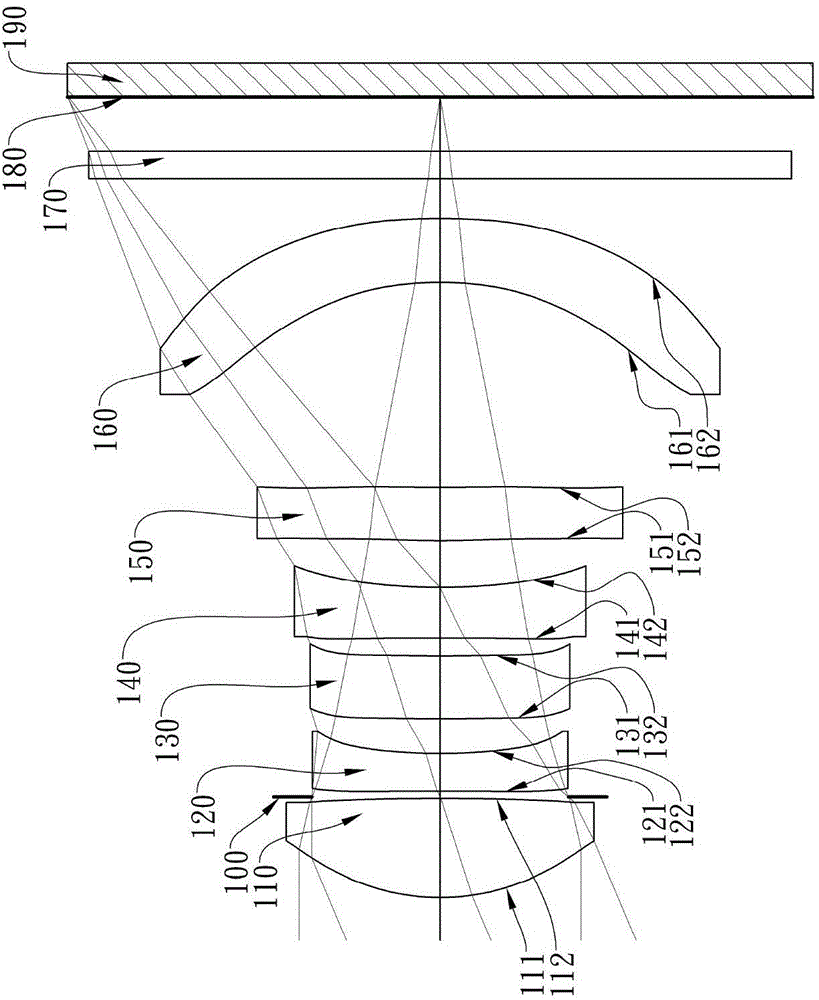
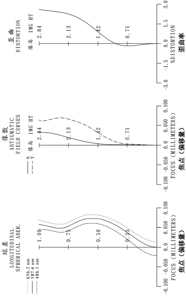
[0104] Please refer to the first embodiment of the present invention Figure 1A , for the aberration curve of the first embodiment, please refer to Figure 1B . The imaging device of the first embodiment includes an imaging lens system (not otherwise labeled) and an electronic photosensitive element 190. The imaging lens system includes a first lens 110, an aperture 100, a second Lens 120, the third lens 130, the fourth lens 140, the fifth lens 150, the sixth lens 160, the infrared filter element 170 and the imaging surface 180, and any two adjacent lenses have a Air space, where:

[0105] A first lens 110 with positive refractive power is made of plastic, its object side 111 is convex at the near optical axis, its image side 112 is convex at the near optical axis, and its object side 111 and image side 112 are both is aspheric;

[0106] A second lens 120 with negative refractive power is made of plastic, its object side 121 is convex at the near optical axis, its image sid...

no. 2 example 》

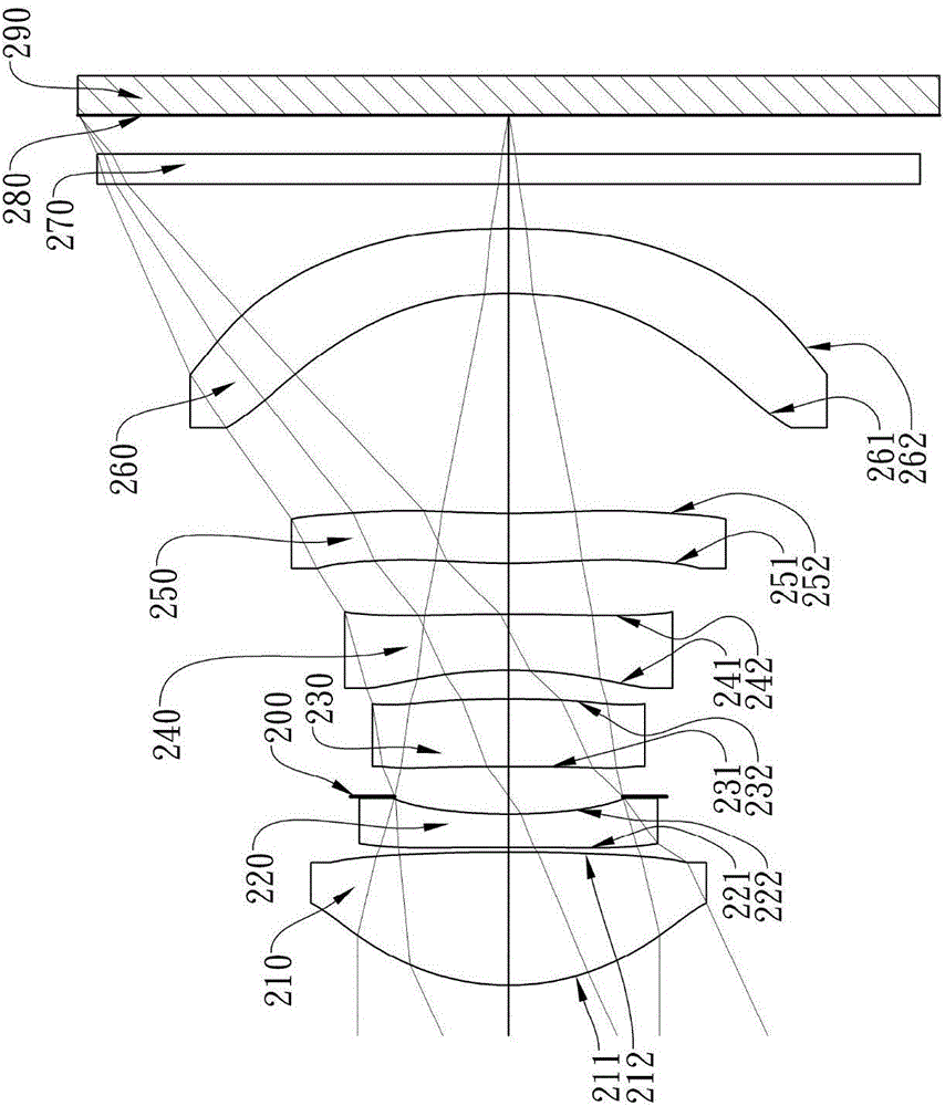
[0141] Please refer to the second embodiment of the present invention Figure 2A , for the aberration curve of the second embodiment, please refer to Figure 2B . The imaging device of the second embodiment includes an imaging lens system (not otherwise labeled) and an electronic photosensitive element 290. The imaging lens system includes a first lens 210, a second lens 220, The aperture 200, the third lens 230, the fourth lens 240, the fifth lens 250, the sixth lens 260, the infrared filter element 270 and the imaging surface 280, and any two adjacent lenses have a Air space, where:

[0142] A first lens 210 with positive refractive power is made of plastic, its object side 211 is convex at the near optical axis, its image side 212 is convex at the near optical axis, and its object side 211 and image side 212 are both is aspheric;

[0143] A second lens 220 with negative refractive power is made of plastic, its object side 221 is convex at the near optical axis, its imag...

no. 3 example 》

[0156] Please refer to the third embodiment of the present invention Figure 3A , for the aberration curve of the third embodiment, please refer to Figure 3B . The imaging device of the third embodiment includes an imaging lens system (not otherwise labeled) and an electronic photosensitive element 390. The imaging lens system includes an aperture 300, a first lens 310, a second lens 310, and Lens 320, the third lens 330, the fourth lens 340, the fifth lens 350, the sixth lens 360, the infrared filter element 370 and the imaging surface 380, and any two adjacent lenses have a Air space, where:

[0157] A first lens 310 with positive refractive power is made of plastic, its object side 311 is convex at the near optical axis, its image side 312 is concave at the near optical axis, and its object side 311 and image side 312 are both is aspheric;

[0158] A second lens 320 with negative refractive power is made of plastic, its object side 321 is convex at the near optical axi...


PUM


Abstract

The invention provides an image sampling lens system, an image sampling device and an electronic device. The image sampling lens system sequentially comprises a first lens, a second lens, a third lens, a fourth lens, a fifth lens and a sixth lens from the object side to the image side. The first lens has a positive refractive power, and the object-side surface of the first lens is a convex surface. The second lens has a negative refractive power. The third lens has a refractive power, and both the object-side surface and image-side surface of the third lens are aspheric surfaces. The fourth lens has a negative refractive power, and both the object-side surface and image-side surface of the fourth lens are aspheric surfaces. The fifth lens has a refractive power, and both the object-side surface and image-side surface of the fifth lens are aspheric surfaces. The sixth lens has a refractive power, and the object-side surface of the sixth lens is a concave surface. The image-side surface of the sixth lens is a convex surface. Both the object-side surface and image-side surface of the sixth lens are aspheric surfaces. In the foregoing configuration condition, the converging ability of the whole system is focused on the object-side end of the lens, and the volume of the system can be effectively controlled. Therefore, the carrying convenience is improved. In addition, the chromatic aberration of the system and the peripheral focusing positions of an image are corrected. At the same time, the bending of peripheral images is avoided.

Description

technical field [0001] The present invention relates to an imaging lens system and an image capturing device, in particular to an imaging lens system and an image capturing device applicable to electronic devices. Background technique [0002] With the gradual thinning of personal electronic products, the internal components of electronic products are required to have a smaller size. Under the market trend, the size of the imaging lens system must be miniaturized. In addition to the requirement of miniaturization, the pixel area of ​​the photosensitive element is reduced due to the advancement of semiconductor process technology, and the imaging lens is gradually developing into the field of high pixel. At the same time, the rise of electronic devices such as smart phones and tablet computers also increases the demand for high-quality micro-image pickup lens systems. [0003] At present, most of the lenses equipped with portable electronic products on the market pursue the...

Claims


Application Information

Patent Timeline
IPC IPC(8): G02B13/00G02B13/18
Inventor 陈俊谚黄歆璇
Owner LARGAN PRECISION
Learn More