Method for actually compensating for geometrical errors of five-axis numerical control tooth manufacturing machine tool through inverse kinematics

An inverse kinematics and geometric error technology, applied in program control, computer control, general control systems, etc., can solve problems such as difficult to meet real-time compensation, no mapping relationship between motion axis error and gear processing error, and large amount of calculation

Active Publication Date: 2017-01-11
NANJING GONGDA CNC TECH
View PDF5 Cites 38 Cited by
  • Summary
  • Abstract
  • Description
  • Claims
  • Application Information

AI Technical Summary

Problems solved by technology

[0004] The existing tool / workpiece pose deviation is calculated by the forward solution of the motion axis error, and the mapping relationship between the motion axis error and the gear machining error has not been established, so it cannot be accurately applied to the correction of the gear machining error
At the same time, the existing motion axis error compensation methods are cumbersome to calculate, have a large amount of calculation, and take a long time. There are differential methods, or iterative and recursive methods, which are difficult to meet the needs of real-time compensation. Therefore, there is an urgent need for a gear-oriented high-precision machining. Error Compensation Method for Real-time Compensation Requirements

Method used


Image

  • Method for actually compensating for geometrical errors of five-axis numerical control tooth manufacturing machine tool through inverse kinematics
  • Method for actually compensating for geometrical errors of five-axis numerical control tooth manufacturing machine tool through inverse kinematics
  • Method for actually compensating for geometrical errors of five-axis numerical control tooth manufacturing machine tool through inverse kinematics

Examples


Embodiment Construction

[0061] In order to make the technical solutions of the present invention clearer, the following describes the technical content of the present invention with reference to the accompanying drawings. It should be understood that the embodiments described herein are only used to explain the present invention, but not to limit the concept and application scope of the present invention.

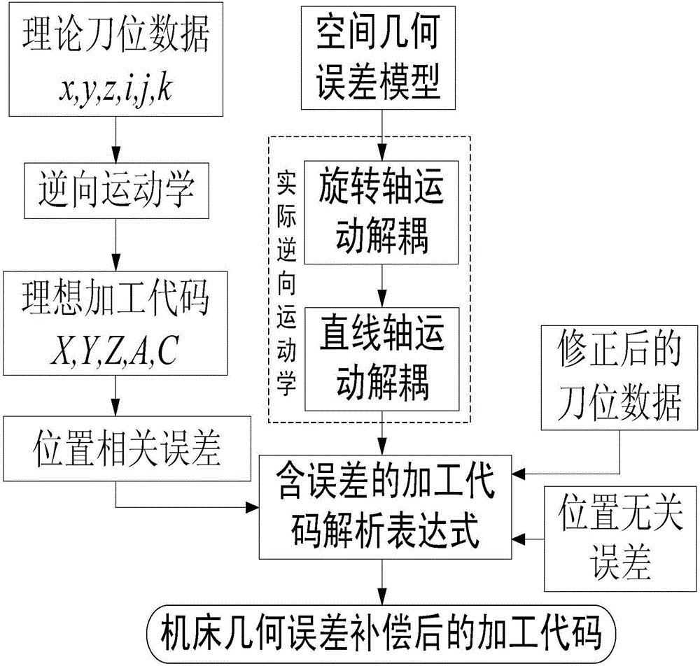
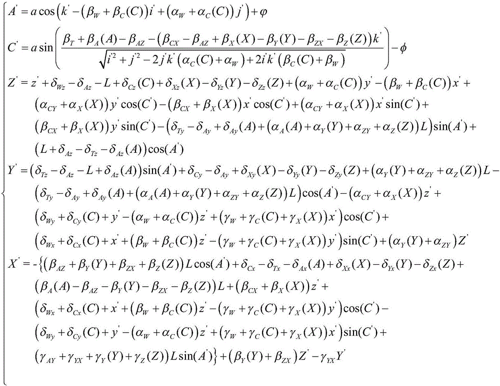
[0062] By establishing a machine tool error kinematic model, the invention solves the motion axis code in the error model, the machine tool geometric error element and the corrected tool position data according to the principles of reversible calculation of homogeneous transformation matrix, associative law, block calculation, etc. Coupling, step-by-step solution to get the analytic expressions of the rotary axis and linear axis code, to achieve rapid compensation of the geometric error of the gear machine tool.

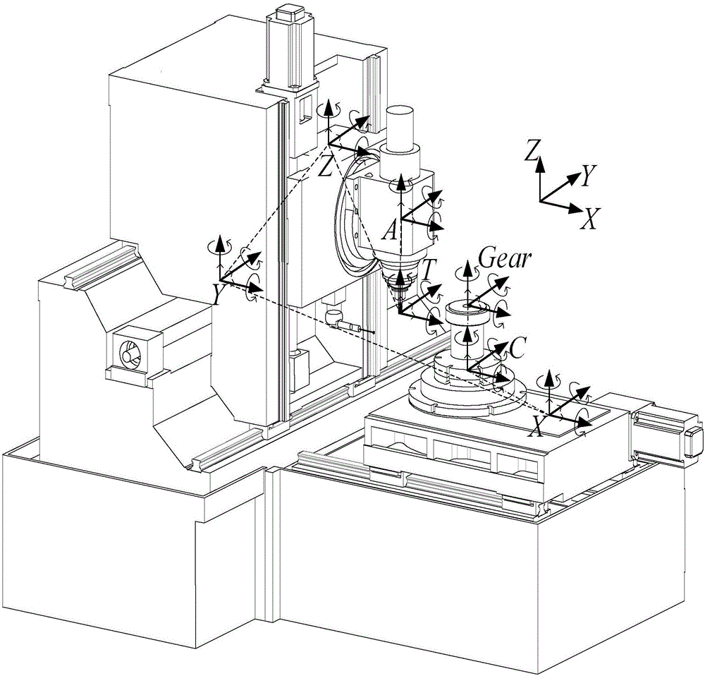
[0063] like figure 2 The shown machine tool axis configuration, taking the X axis ...


PUM


Abstract

The invention provides a method for actually compensating for geometrical errors of a five-axis numerical control tooth manufacturing machine tool through the inverse kinematics. The method includes the steps of building a space geometrical error model containing position unrelated errors and position related errors on the basis of a homogeneous coordinate transformational matrix, and deducing a processing code analytical expression containing the geometrical errors from the space geometrical error model according to the characteristics of the homogeneous coordinate transformational matrix. Theoretical cutter location data is modified by 12 pose deviations (6 static pose deviations and 6 movement pose deviations) of a cutter relative to a workpiece. The geometrical errors of the machine tool can be compensated for by substituting the position unrelated errors, the position related errors and the modified cutter location data into the processing code analytical expression for compensating for the geometrical errors of the machine tool, and meanwhile the12 pose deviations of the cutter relative to the workpiece are modified. The error compensation method is simple in compensation process, easy to understand, small in calculation amount, high in compensation efficiency and wide in application range, and the basic compensation concept of the method is suitable for numerical control machine tools of various types.

Description

technical field [0001] The invention belongs to the field of machine tool geometric error compensation, in particular to an actual inverse kinematics compensation method for geometric error of a five-axis numerically controlled gear machine tool, which is a method for improving gear machining accuracy by compensating for the geometric error of a gear machine tool. Background technique [0002] In the process of machine tool machining, geometric errors always affect the machining accuracy of parts, and the compensation of machine tool geometric errors is an effective measure to improve machining accuracy. The most direct reason for the occurrence of machine tool machining errors is that the ideal mutual pose relationship between the tool and the workpiece has changed. To study the influence of the machine tool axis errors on the machining accuracy, the essence is to study the relative relationship between the machine tool axis errors on the tool and the workpiece. The influen...

Claims


Application Information

Patent Timeline
Patent Type & Authority Applications(China)
IPC IPC(8): G05B19/404
CPCG05B19/404G05B2219/37068G05B2219/37581
Inventor 黄筱调丁爽于春建
Owner NANJING GONGDA CNC TECH
Why Eureka
Try Eureka