Power capacitor placing heat dissipation device

A technology of heat dissipation device and capacitor, applied in the direction of capacitors, electrical components, etc., can solve the problems of incomplete heat dissipation, difficult heat dissipation, complicated operation, etc., and achieve the effect of improving work efficiency

Inactive Publication Date: 2017-01-11
刘飞
View PDF4 Cites 9 Cited by
  • Summary
  • Abstract
  • Description
  • Claims
  • Application Information

AI Technical Summary

Problems solved by technology

[0008] In order to overcome the shortcomings of incomplete heat dissipation, difficulty in timely heat dissipation and complicated operation of the existing placed heat sink, the technical problem to be solved by the present invention is to provide a placed heat sink for electric power capacitors that can completely dissipate heat, can dissipate heat in time, and is easy to operate

Method used


Image

  • Power capacitor placing heat dissipation device
  • Power capacitor placing heat dissipation device
  • Power capacitor placing heat dissipation device

Examples


Embodiment 1

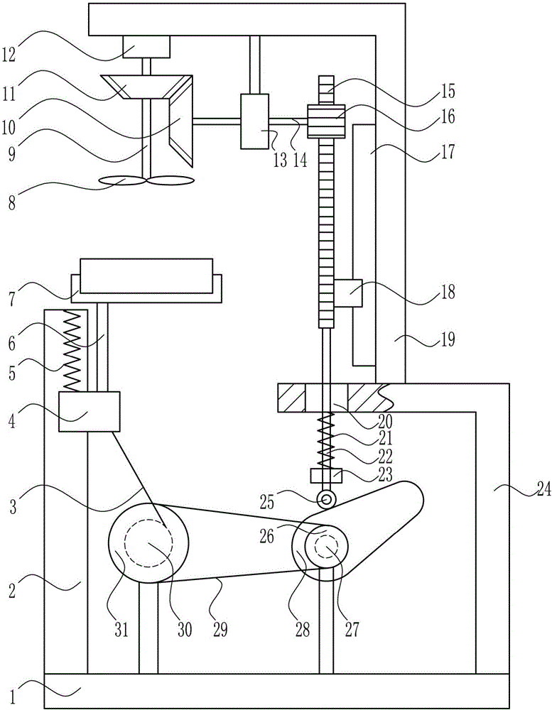
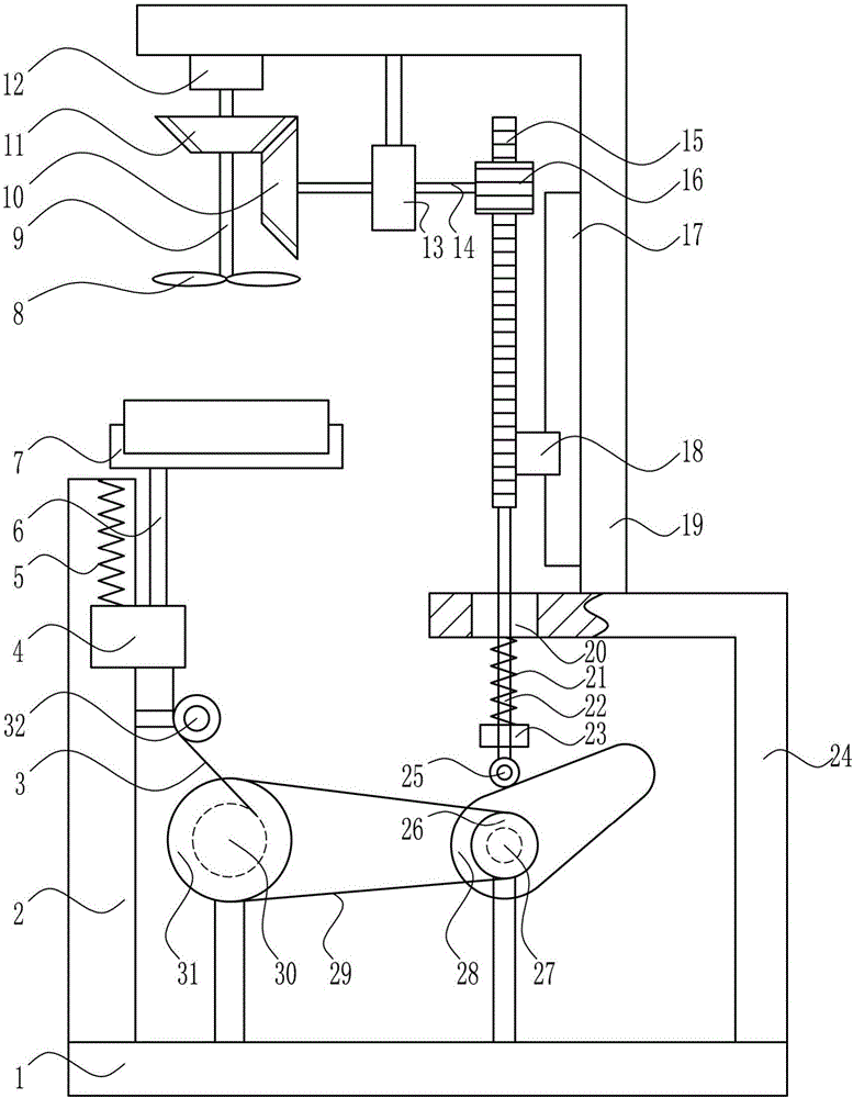
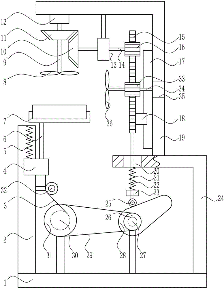
[0035] A cooling device for placing capacitors for electric power, such as Figure 1-4As shown, it includes a bottom plate 1, a first slide rail 2, a pull wire 3, a first slider 4, a first spring 5, a pole 6, a placement tank 7, a first blade 8, a first rotating shaft 9, and a second cone Gear 10, first bevel gear 11, first bearing seat 12, second bearing seat 13, second rotating shaft 14, rack 15, first gear 16, second slide rail 17, second slider 18, second L Shaped frame 19, second spring 21, elevating lever 22, fixed block 23, first L-shaped frame 24, contact roller 25, small pulley 26, motor 27, cam 28, flat belt 29, reel 30 and large pulley 31, the top of the bottom plate 1 is provided with the first slide rail 2, the winding wheel 30, the motor 27 and the first L-shaped frame 24 in sequence from left to right, the first slide rail 2 is provided with the first slider 4, the first slide The first spring 5 is connected between the top of the block 4 and the first slide ra...


PUM


Abstract

The invention relates to a placing heat dissipation device, and particularly relates to a power capacitor placing heat dissipation device. The technical problem to be solved by the invention is to provide a power capacitor placing heat dissipation device, which dissipates heat thoroughly, can dissipate heat in time and is simple and convenient in operation. In order to solve the technical problem, the power capacitor placing heat dissipation device comprises a bottom plate, a first slide rail, a stay wire, a first slide block, a first spring, a supporting rod, a placing trough body, a first blade, a first rotating shaft, a second bevel gear, a first bevel gear and the like; the first slide rail, a reel, a motor and a first L-shaped rack are arranged at the top of the bottom plate in sequence from left to right; and the first slide block is arranged on the first slide rail. The device dissipates heat thoroughly, can dissipate heat in time and is simple and convenient in operation; when the device is used, comprehensive heat dissipation can be performed on a capacitor, so that the service life of the capacitor can be prolonged.

Description

technical field [0001] The invention relates to a cooling device for placement, in particular to a cooling device for placing capacitors used in electric power. Background technique [0002] Electricity is an energy source powered by electrical energy. It converts the primary energy of nature into electricity through mechanical energy devices, and then supplies electricity to various users through power transmission, transformation and distribution. [0003] Capacitors, usually referred to as capacitance for their ability to hold charges, are denoted by the letter C. Definition 1: A capacitor, as the name implies, is a 'charged container', a device that holds charges. Capacitors are one of the electronic components widely used in electronic equipment, and are widely used in DC blocking, coupling, bypass, filtering, tuning loops, energy conversion and control in circuits. Definition 2: Capacitor, any two conductors that are insulated from each other and are very close to e...

Claims


Application Information

Patent Timeline
Patent Type & Authority Applications(China)
IPC IPC(8): H01G2/08
CPCH01G2/08
Inventor 刘飞
Owner 刘飞
Why Eureka
Try Eureka