Eureka AIR delivers breakthrough ideas for toughest innovation challenges, trusted by R&D personnel around the world.

Microstrip printing dipole antenna

A technology of dipole antenna and microstrip transmission line, applied in the field of communication, can solve the problem of large size of printed dipole antenna

Inactive Publication Date: 2017-01-11
ANHUI SAFE ELECTRONICS
View PDF2 Cites 1 Cited by
  • Summary
  • Abstract
  • Description
  • Claims
  • Application Information

AI Technical Summary

Problems solved by technology

[0003] Most of today's electronic products are developing in the direction of miniaturization, but the existing printed dipole antennas are large in size, so there is an urgent need for a small and compact printed dipole antenna

Method used


Image

  • Microstrip printing dipole antenna
  • Microstrip printing dipole antenna

Examples


Embodiment Construction

[0014] The present invention will be further described below with reference to the accompanying drawings.

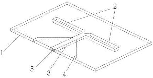
[0015] like figure 1 Shown, a kind of microstrip printed dipole antenna, this dipole antenna comprises printing plate 1, and the two sides of printing plate 1 are symmetrically attached the metal transmission line of good conductor, and metal transmission line constitutes two of described dipole antennas. arm 2, microstrip transmission line 3 and two microstrip baluns 4, the microstrip transmission line 3 is a double transmission line structure, and the two arms 2 and two microstrip baluns 4 of the dipole antenna are symmetrically arranged on the microstrip At both ends of the transmission line 3 , the microstrip balun 4 is in the shape of a right-angled trapezoid and the bottom of the trapezoid is connected to the microstrip transmission line 3 .

[0016] The end surface of the microstrip transmission line 3 located on the surface of the printing plate 1 is a wireless ...


PUM


Abstract

The invention provides a microstrip printing dipole antenna. The dipole antenna comprises a printing plate, two surfaces of the printing plate are symmetrically provided with metal transmission lines of good conductors, the metal transmission lines form two arms of the dipole antenna, a microstrip transmission line, and two microstrip baluns, the microstrip transmission line is a double-transmission-line structure, two arms of the dipole antenna and two microstrip baluns are respectively and symmetrically arranged at two ends of the microstrip transmission line, the microstrip baluns are in the shape of right angle trapezoids, and the lower bottoms of the trapezoids are connected to the microstrip transmission line. The microstrip printing dipole antenna is advantaged by light weight, small size, low cost, convenient integration and array composition, and the application demand of miniaturization of electronic products is met.

Description

technical field [0001] The invention relates to the technical field of communication, in particular to a microstrip printed dipole antenna. Background technique [0002] Dipole antennas are used to transmit and receive fixed frequency signals. Although wideband antennas are used in usual measurements, dipole antennas are required to be used in site attenuation and antenna coefficient measurements. As people's requirements for communication quality and integration of communication equipment continue to increase. As a sub-component of communication equipment, antennas also require higher performance to meet the needs of communication systems. Nowadays, a printed dipole antenna has appeared, which prints dipoles on a thin dielectric substrate. It is light in weight, easy to process and provides a wide bandwidth and advanced purity. The structure of the antenna is: With the printed board as the support, the dipole is set on one side, and the matching feeder is set on the othe...

Claims


Application Information

Patent Timeline
IPC IPC(8): H01Q1/38H01Q1/50H01Q9/20
CPCH01Q1/38H01Q1/50H01Q9/20
Inventor 周峰曹骏骅
Owner ANHUI SAFE ELECTRONICS
Why Eureka
Eureka Blog
Learn More