An automatic welding device for cable joints

An automatic welding and cable joint technology, which is applied in the direction of connection, line/collector parts, electrical components, etc., can solve the problems of high cable joint welding rejection rate, low welding accuracy, low degree of automation, etc., and achieve processing The effect of low efficiency, high welding accuracy and high processing cost

Active Publication Date: 2018-08-14
GANZHOU JINXINNUO CABLE TECH
View PDF3 Cites 0 Cited by
  • Summary
  • Abstract
  • Description
  • Claims
  • Application Information

AI Technical Summary

Problems solved by technology

[0006] In order to overcome the disadvantages of high cable joint welding rejection rate, low processing efficiency and high processing cost under the existing technical conditions, the present invention consumes a lot of manpower and material resources, has low degree of automation, and low welding precision. The technical problem to be solved by the invention is to provide an automatic cable joint welding device with high degree of automation, high processing efficiency and high welding precision

Method used


Image

  • An automatic welding device for cable joints

Examples


Embodiment 1

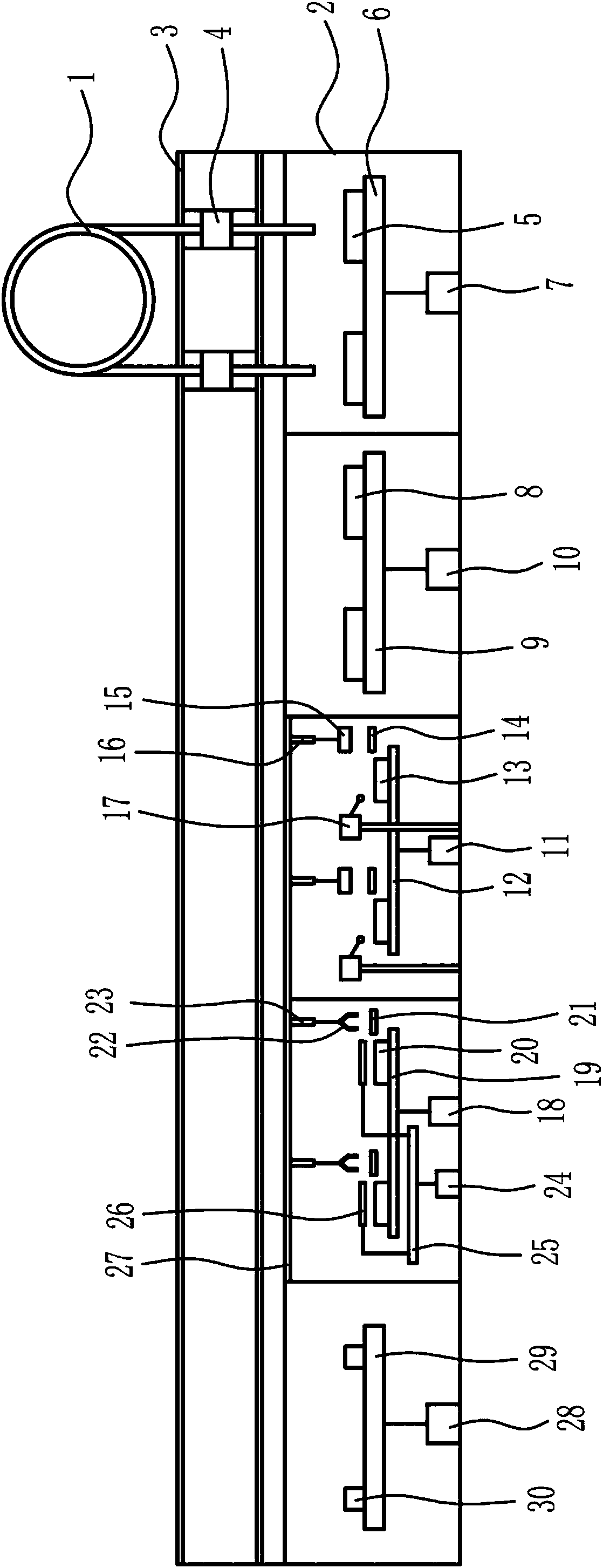
[0017]An automatic welding device for cable joints, as shown in Figure 1, includes a frame 2, a horizontal slideway I3, a wire clamping device 4, a wire stripping machine I5, a support plate I6, a cylinder I7, a wire stripping machine II8, and a support plate Ⅱ9, cylinder Ⅱ10, cylinder Ⅲ11, support plate Ⅲ12, welding table Ⅰ13, transmission device Ⅰ14, electric gripper 15, electric push rod Ⅰ16, welding device 17, cylinder Ⅳ18, support plate Ⅳ19, welding table Ⅱ20, transmission device Ⅱ21, manipulator 22. Electric push rod Ⅱ23, cylinder Ⅴ24, support plate Ⅴ25, induction coil 26, horizontal slideway Ⅱ27, cylinder Ⅵ28, support plate Ⅵ29 and detection device 30; horizontal slideway Ⅰ3 is arranged above the frame 2, and horizontal slideway Ⅰ3 There are wire clamping devices 4 symmetrically arranged on the left and right, and a wire stripping machine Ⅰ5 is installed under the wire clamping devices 4. A support plate Ⅰ6 is provided under the wire stripping machine Ⅰ5, and a cylinder ...


PUM


Abstract

The invention relates to a welding device, in particular to an automatic welding device of a cable joint. The automatic welding device aims to solve the technical problem that the automatic welding device, which has the advantages of high automation degree, high processing efficiency and high welding accuracy, of the cable joint is provided. The device comprises a rack, a first horizontal slideway, wire clamping devices, first wire-stripping machines, a first supporting plate, a first cylinder and the like, wherein the first horizontal slideway is arranged above the rack; the first horizontal slideway is bilaterally provided with the wire clamping devices; one first wire-stripping machine is independently arranged below each wire clamping device; the first supporting plate is arranged below the first wire-stripping machines; the first cylinder is connected below the first supporting plate; and the other end of the first cylinder is arranged on the rack. By use of the automatic welding device, the defects of manpower and material resource consumption, low automation degree, low welding accuracy, high rejection rate, low processing efficiency and high processing cost of cable joint welding are solved, and the effects of high automation degree, high processing efficiency and high welding accuracy are realized.

Description

technical field [0001] The invention relates to a welding device, in particular to an automatic welding device for cable joints. Background technique [0002] The cable is generally composed of a core, an inner sheath, an armor layer and an outer sheath. There are many uses of cables, mainly used for multiple functions such as control installation, connection equipment, power transmission, etc., which are common and indispensable in daily life. After the cable is laid, in order to make it a continuous line, each section of the line must be connected as a whole, and these connection points are called cable joints. The cable joints in the middle of the cable line are called intermediate joints, and the cable joints at both ends of the line are called terminal heads. The cable connector is used to lock and fix the incoming and outgoing wires, so as to play the role of waterproof, dustproof and shockproof. The cable end part is generally composed of the wire core and the cent...

Claims


Application Information

Patent Timeline
Patent Type & Authority Patents(China)
IPC IPC(8): H01R43/02
CPCH01R43/02H01R43/0263
Inventor 桂宏兵周俊汪传灯
Owner GANZHOU JINXINNUO CABLE TECH
Why Eureka
Try Eureka