Open circuit failure mode discharge tube

A failure mode, discharge tube technology, applied in the field of discharge tubes, can solve the problems of gas discharge tube short circuit, circuit board burning, affecting safe use, etc., and achieve the effect of a simple overall structure

Active Publication Date: 2017-01-11
SHENZHEN RUILONGYUAN ELECTRONICS
View PDF5 Cites 5 Cited by
  • Summary
  • Abstract
  • Description
  • Claims
  • Application Information

AI Technical Summary

Problems solved by technology

But at the same time, if the overvoltage lasts for a long time or occurs frequently, or if there is a long-term or high current, the gas discharge tube will heat up due to the long-term or frequent

Method used


Image

  • Open circuit failure mode discharge tube
  • Open circuit failure mode discharge tube
  • Open circuit failure mode discharge tube

Examples


Embodiment Construction

[0019] The present invention will be described in further detail below in conjunction with the accompanying drawings.

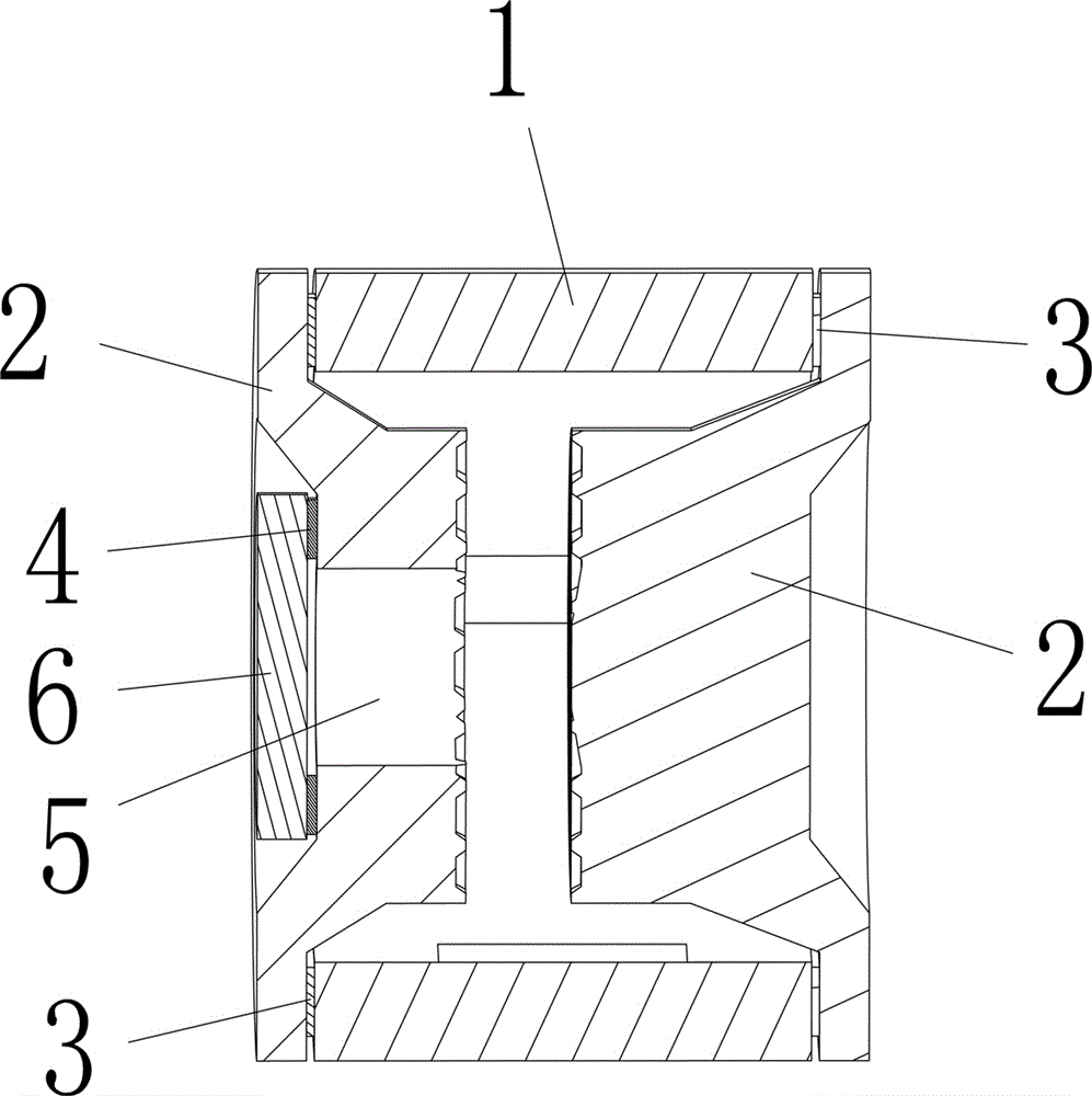
[0020] First of all, it should be noted that the high-temperature solder and low-temperature solder referred to in the present invention refer to the melting point of the solder, and high temperature and low temperature are relative. For the present invention, what is required is the ratio of the melting point of the solder that fixes the metal sheet to The melting point of the solder for the fixed electrode and the insulating tube body should be low, and according to different discharge tubes and the environment in which they are used, the melting point of the high-temperature solder and the low-temperature solder can be selected according to the actual situation, and will not be repeated here. Reference may also be made to the prior art in the Background Art. The high-temperature solder in the present invention may be a high-temperature solder sheet, and th...


PUM


Abstract

The invention discloses an open circuit failure mode discharge tube. The open circuit failure mode discharge tube comprises at least one insulating tube body and two electrodes. The two electrodes are connected with the two ends of the insulating tube body in a sealed mode respectively to form a discharge inner cavity. The two electrodes are connected with the insulating tube body in the sealed mode through high-temperature welding flux, the emitting surface of the inner side of at least one electrode is provided with a through hole penetrating through the outer side of the electrode, and a metal sheet is fixed to the outer side of the corresponding electrode through low-temperature welding flux to close and seal the through hole. The overall structure is simple, the through hole is formed in the corresponding electrode, the metal sheet seals and covers the through hole through the low-temperature welding flux, when the discharge tube generates heat, the low-temperature welding flux is melted, the metal sheet is popped up through gas obtained after heating expansion in the discharge cavity, and external air enters the discharge cavity to enable discharge to fail, so that an open circuit is formed.

Description


Claims


Application Information

Patent Timeline
Owner SHENZHEN RUILONGYUAN ELECTRONICS
Why Eureka
Try Eureka