
Identification control method of rotational inertia of motor

A technology of moment of inertia and control method, applied in the direction of motor generator control, electronic commutation motor control, vector control system, etc., can solve the problems of inaccuracy, need of EEPROM, inaccurate conclusion, etc., and achieve the effect of correct drive control

Active Publication Date: 2017-01-11
SICHUAN CHANGHONG ELECTRIC CO LTD
View PDF5 Cites 8 Cited by
  • Summary
  • Abstract
  • Description
  • Claims
  • Application Information

AI Technical Summary

Problems solved by technology

When a large number of different motors need to be controlled, the motor parameters are often stored in a similar EEPROM, and the control program is kept unchanged, which can solve the control of motors such as different compressors, but this method has the following technical problems: one is the need EEPROM increases the cost of hardware. Second, when the user’s inverter air conditioner has a problem and needs to be repaired, if the original control board is replaced with a new control circuit or new control software, the specific parameters of the motor may not be known. , unable to quickly replace the motor control circuit and control software
[0004] 1) formula itself is not accurate enough, and all subsequent conclusions are not accurate enough, this is due to the formula Even if ignore B m The term ω cannot obtain the formula
[0005] 2) formula The requirement that "the acceleration times of the first acceleration stage and the second acceleration stage are both 10 milliseconds" is based on making a difference between the formula (2) of the first acceleration stage and the formula (3) of the second acceleration stage to obtain the moment of inertia J, Because in practical applications, the change of torque is generally not faster than 20 milliseconds, that is to say, it can be approximately considered that the torque of the first acceleration stage and are equal, obtained under this assumption, since there are assumptions, there may be conditions that do not match the assumptions, so the conclusions obtained are not reliable

Method used


Image

  • Identification control method of rotational inertia of motor
  • Identification control method of rotational inertia of motor
  • Identification control method of rotational inertia of motor

Examples


Embodiment Construction

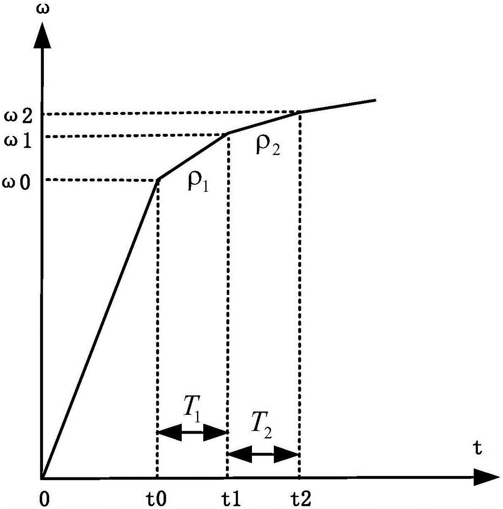
[0018] The invention controls the speed of the motor to accelerate from the stopped state to the specified speed f 0 Hz, from ω 0 =2πf 0 Get the corresponding angular velocity ω 0 , the unit is rad / s, that is, radian / second, such as figure 1 As shown, when the motor speed reaches ω 0 After that, control the motor according to the specified first acceleration ρ 1 speed up, run time is Where n is a positive integer, the same below. That is, the acceleration running time is an integer multiple of the current motor running cycle time, detect and record the d / q axis current during this process; then continue to control the motor according to the specified second acceleration ρ 2 Speed ​​up, ρ 1 ≠ρ 2 , the accelerated running time is the same as Detect and record the d / q axis current during this process, and finally obtain the moment of inertia J of the motor through formula calculation.

[0019] From the motor dynamic equation:

[0020] J d...


PUM


Abstract

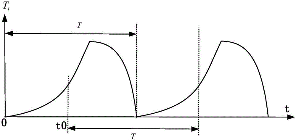
The invention belongs to the air-conditioner control technical field and discloses an identification control method of the rotational inertia of a motor. With the method adopted, problems in automatic acquisition of the rotational inertia of a variable frequency motor can be solved. According to the method, the accelerated velocity and acceleration time of motor rotation velocity in two stages are controlled; motor d / q-axis current corresponding to each fluctuation period of a load torque in each stage is sampled according to the periodicity of the fluctuation of the load torque of the rotor of the motor; and the rotational inertia of the motor is obtained according to the relations of the motor torque and the current, and a motor dynamic equation model. The method of the invention is suitable for determining the rotational inertia of the motor of an air conditioner.

Description

technical field [0001] The invention relates to an air conditioner control technology, in particular to a motor inertial identification control method. Background technique [0002] The traditional variable frequency motor control technology requires the motor manufacturer to provide parameters such as the moment of inertia of the motor, which is determined by the motor dynamics equation Determined, where J is the moment of inertia of the motor, T e is the torque, T l is the load torque, B m is the viscous friction coefficient, and ω is the mechanical angular velocity of the motor. When a large number of different motors need to be controlled, the motor parameters are often stored in a similar EEPROM, and the control program is kept unchanged, which can solve the control of motors such as different compressors, but this method has the following technical problems: one is the need EEPROM increases the cost of hardware. Second, when the user’s inverter air conditioner has...

Claims


Application Information

Patent Timeline
IPC IPC(8): H02P21/00H02P21/14
CPCH02P21/0003H02P21/14
Inventor 陈跃涂小平刘启武唐婷婷朱绯任艳华王璠高向军
Owner SICHUAN CHANGHONG ELECTRIC CO LTD
Learn More