Beam forming method and device

A beamforming and directional beam technology, applied in the field of beamforming methods and devices, can solve the problem of small antenna gain at the transmitting end and the like

Active Publication Date: 2017-01-11
HUAWEI TECH CO LTD
View PDF6 Cites 6 Cited by
  • Summary
  • Abstract
  • Description
  • Claims
  • Application Information

AI Technical Summary

Problems solved by technology

[0006] In order to solve the problem of small antenna gain at the transmitting end, the present invention provides a beamforming method and device

Method used


Image

  • Beam forming method and device
  • Beam forming method and device
  • Beam forming method and device

Examples


Embodiment Construction

[0086] The following will clearly and completely describe the technical solutions in the embodiments of the present invention with reference to the drawings in the embodiments of the present invention. Obviously, the described embodiments are part of the embodiments of the present invention, not all of them. Based on the embodiments of the present invention, all other embodiments obtained by persons of ordinary skill in the art without making creative efforts shall fall within the protection scope of the present invention.

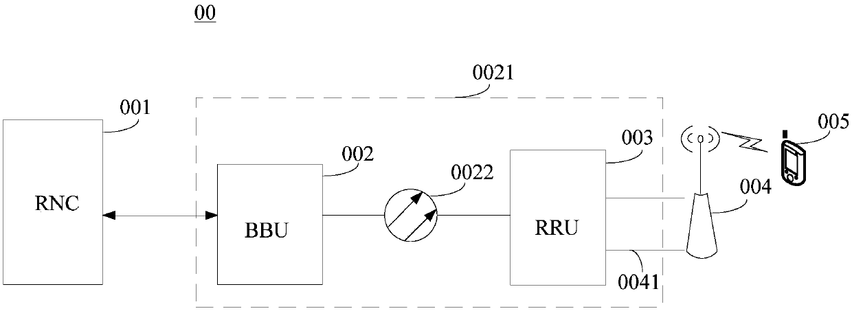
[0087] It should be understood that the technical solutions of the embodiments of the present invention can be applied to various communication systems, for example: Wideband Code Division Multiple Access (English: Wideband Code Division Multiple Access, referred to as: WCDMA) system, Code Division Multiple Access (English: Code Division Multiple Access) Access 2000; abbreviation: CDMA2000) system, time division synchronous code division multiple access (En...


PUM


Abstract

The invention discloses a beam forming method and device, and belongs to the field of wireless communication. The method comprises the following steps: determining a channel matrix of a first reference signal; using a product of a preset directional beam weight vector matrix and a directional beam weighted coefficient matrix as a model matrix of a beam forming weight; using a product of the model matrix of the beam forming weight and a detection reference signal coefficient matrix H<SRS> as a channel matrix of a data signal; determining the model matrix of the beam forming weight satisfying a constraint relationship as a beam forming weight matrix according to the channel matrix of the first reference signal, the channel matrix of the data signal and a preset constraint relationship between the channel matrix of the first reference signal and the channel matrix of the data signal; and performing beam forming processing on the data signal according to the beam forming weight matrix. Through adoption of the beam forming method and device, the problem of relatively small antenna gain of a transmitting end is solved, and the effects of obtaining narrower beams, concentrating energy and increasing the antenna gain of the transmitting end are achieved. The beam forming method and device are applied to an MIMO (Multiple-Input Multiple-Output) system.

Description

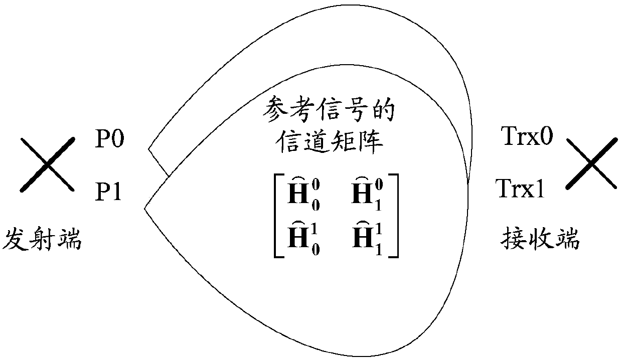
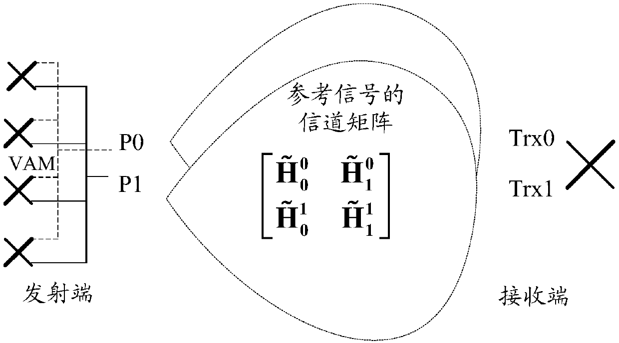
technical field [0001] The present invention relates to the field of wireless communication, in particular to a beam forming method and device. Background technique [0002] Multiple-Input Multiple-Output (English: Multiple-Input Multiple-Output; abbreviation: MIMO) technology uses multiple transmitting antennas and receiving antennas at the transmitting end and receiving end respectively, so that signals are transmitted and received through multiple antennas at the transmitting end and receiving end. , thus improving the communication quality. figure 1 A schematic structural diagram of a MIMO system of 2*2 (that is, 2 inputs and 2 outputs) is shown, wherein P0 and P1 are transmit ports, Trx0 and Trx1 are receive ports, and the matrix H ~ 0 0 H ~ 1 ...

Claims


Application Information

Patent Timeline
Patent Type & Authority Applications(China)
IPC IPC(8): H04B7/06H04W16/28H04B7/04
CPCH04B7/04H04B7/0617H04B7/0413H04B7/063H04W16/28
Inventor 张鹏程
Owner HUAWEI TECH CO LTD
Why Eureka
Try Eureka