
Adaptive equalizer and method for realizing adaptive equalization processing by the adaptive equalizer

An adaptive equalization and filter processing technology, which is applied in the shaping network, optical fiber transmission, transmission system, etc.

Active Publication Date: 2017-01-11
ZTE CORP
View PDF4 Cites 11 Cited by
  • Summary
  • Abstract
  • Description
  • Claims
  • Application Information

AI Technical Summary

Problems solved by technology

[0006] Judging from the above related technologies for monitoring and intervening in the working process of the adaptive equalizer, the system needs the convergence of the second adaptive equalizer. In this way, not only the process is complicated and the time to enter the system stability is affected, but also depends on the initial convergence Post-frame positioning feedback skew value between polarization states
In addition, since the error signal is obtained by calculating the two polarization states together, the fine-tuning of the coefficients and the movement of integer multiples of the sample point are carried out in one direction for the polarization state coefficients, which is not flexible enough to cover all channel scenarios
Moreover, after moving the coefficients to an integer multiple of samples, the method of directly padding the filter output with zeros will cause large bit errors due to the lack of consideration of the energy of the shifted coefficients, which will affect the performance of the back-end module.
[0007] That is to say, the existing technology cannot effectively solve the problems of adjusting the coefficients to the center of the coefficient taps and not having a large impact on system errors after the coefficients are adjusted.

Method used


Image

  • Adaptive equalizer and method for realizing adaptive equalization processing by the adaptive equalizer
  • Adaptive equalizer and method for realizing adaptive equalization processing by the adaptive equalizer
  • Adaptive equalizer and method for realizing adaptive equalization processing by the adaptive equalizer

Examples


Embodiment Construction

[0109] In order to make the purpose, technical solution and advantages of the present invention more clear, the embodiments of the present invention will be described in detail below in conjunction with the accompanying drawings. It should be noted that, in the case of no conflict, the embodiments in the present application and the features in the embodiments can be combined arbitrarily with each other.

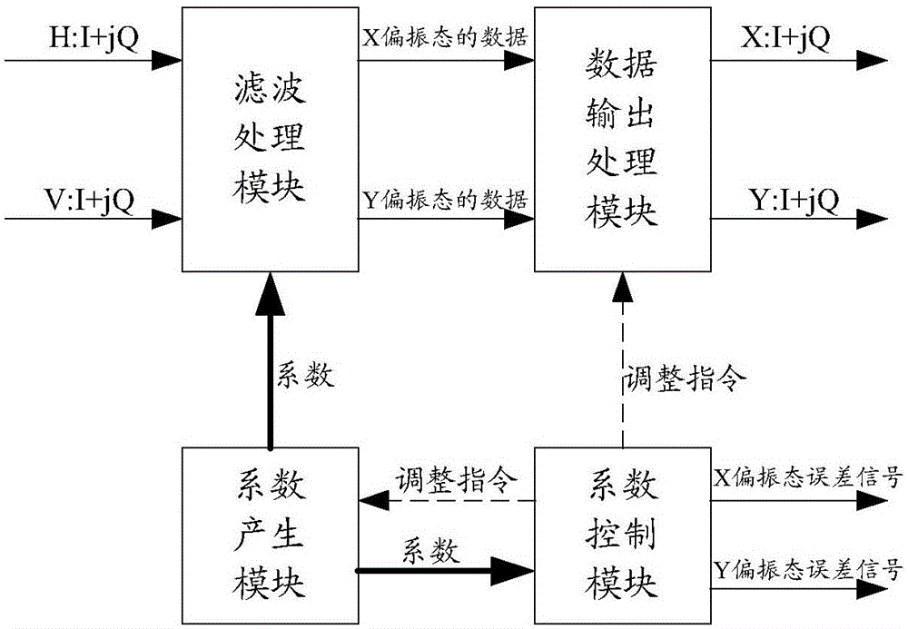
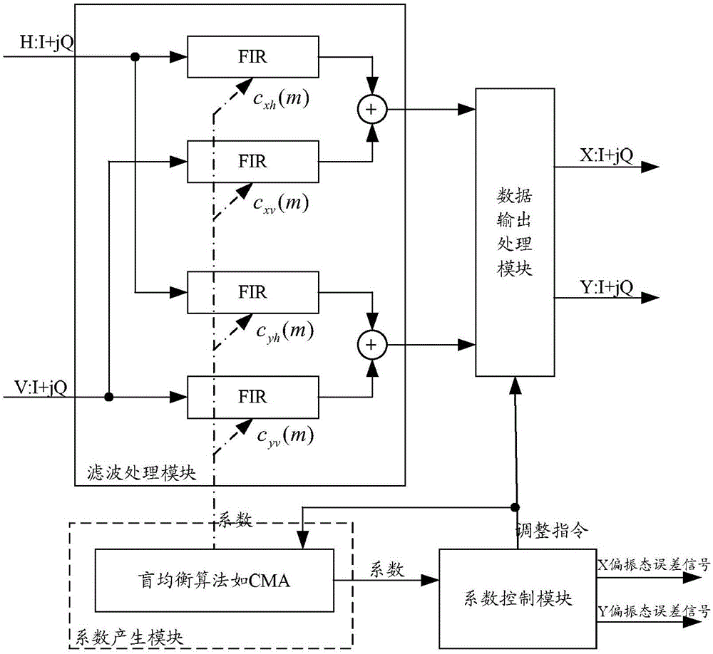
[0110] figure 2 It is a schematic diagram of the composition and structure of the adaptive equalizer of the present invention, including at least a coefficient generation module, a filter processing module, a coefficient control module, and a data output processing module; wherein,

[0111] A coefficient generation module, used to calculate the coefficients required for filter processing, and output to the filter processing module and the coefficient control module; wherein, the coefficients include the coefficient c that maps H to X xh (m), the coefficient c of V mapped to...


PUM


Abstract

The invention discloses an adaptive equalizer and a method of realizing adaptive equalization processing by the adaptive equalizer. The method comprises the steps obtaining an X polarization state error signal and a Y polarization state error signal according to the first distance between a calculated coefficient centre of gravity mapped from H and V to X and a coefficient tap center, and the second distance between the calculated coefficient centre of gravity mapped from H and V to Y and the coefficient tap center; and carrying out interpolation processing on data of an X polarization state and the data of a Y polarization state in clock synchronous processing. According to the technical scheme of the equalizer and the method, the X polarization state and the Y polarization state are taken into consideration for error calculation, the data of the X polarization state and the data of the Y polarization state are adjusted, and the coefficients of the X polarization state and the Y polarization state are flexibly and effectively controlled to be close to a tap center location. Further, according to the equalizer and the method, the coefficients and output data are adjusted according to the coefficient energy mapped from the H and V to the X, and the coefficient energy mapped from the H and V to the Y, when the coefficient energy is on a tap boundary.

Description

technical field [0001] The invention relates to high-speed optical transmission technology, in particular to an adaptive equalizer and a method for realizing adaptive equalization processing thereof. Background technique [0002] In high-speed optical transmission systems, coherent receivers need to compensate for various impairments in the optical channel, such as polarization film dispersion (PMD, Polarization Mode Dispersion), chromatic dispersion (CD, Chromatic Dispersion) and polarization-dependent loss (PDL, Polarization Dependent Loss )Wait. The adaptive equalizer uses a digital signal processing (DSP, Digital Signal Processing) technology to adaptively track channel characteristics, so as to achieve the function of compensating various impairments in the channel. [0003] figure 1 It is a schematic diagram of the composition function of the existing coherent receiver, such as figure 1 As shown, the input signal of the receiver is the polarization state horizontal ...

Claims


Application Information

Patent Timeline
IPC IPC(8): H04B10/2507H04B10/2569
CPCH04B10/616H04L25/03019H04L25/03
Inventor 王卫明
Owner ZTE CORP
Learn More