Optical module and optical signal output control method

An optical module and optical signal technology, which is applied in the field of optical communication and can solve problems such as wavelength drift of optical signals

Active Publication Date: 2017-01-11
HISENSE BROADBAND MULTIMEDIA TECH
View PDF5 Cites 13 Cited by
  • Summary
  • Abstract
  • Description
  • Claims
  • Application Information

AI Technical Summary

Problems solved by technology

[0013] Aiming at the shortcomings of the prior art, the present invention proposes an optical module and its optical signal output control method to s

Method used


Image

  • Optical module and optical signal output control method
  • Optical module and optical signal output control method
  • Optical module and optical signal output control method

Examples


Embodiment Construction

[0032] Embodiments of the present invention are described in detail below, examples of which are shown in the drawings, wherein the same or similar reference numerals designate the same or similar elements or elements having the same or similar functions throughout. The embodiments described below by referring to the figures are exemplary only for explaining the present invention and should not be construed as limiting the present invention.

[0033] Those skilled in the art will understand that unless otherwise stated, the singular forms "a", "an", "said" and "the" used herein may also include plural forms. It should be further understood that the word "comprising" used in the description of the present invention refers to the presence of said features, integers, steps, operations, elements and / or components, but does not exclude the presence or addition of one or more other features, Integers, steps, operations, elements, components, and / or groups thereof. It will be unders...


PUM


Abstract

An embodiment of the present invention provides an optical module and an optical signal output control method thereof. The optical module comprises a distributed Bragg reflective DBR laser, a driving circuit for supplying a driving current to the active region of the laser, a first current source, a second current source, and a circuit switching unit. The first and second current sources are used for outputting a first current and a second current. The two input ends of the circuit switching unit are respectively connected to the current output ends of the first and second current sources. The output end of the circuit switching unit is connected to the DBR area of the laser. The circuit switching unit is used for connecting the current output end of the first current source to the DBR area of the laser to output the first current to allow the laser to transmit an optical signal with operating wavelength, after an optical transmitting signal is received. The circuit switching unit is further used for connecting the DBR current output end of the second current source to the DBR area of the laser to output the second current to allow the laser to transmit an optical signal with non-operating wavelength, after an optical stopping signal is received. The optical module is operated in a burst mode and wavelength shift of the optical signal emitted by the laser is small.

Description

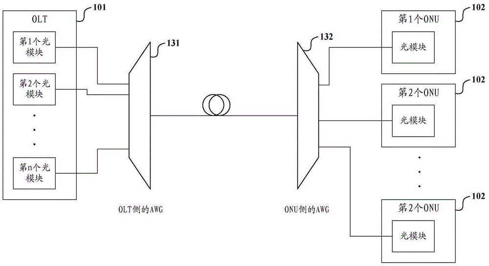
technical field [0001] The present invention relates to the technical field of optical communication, in particular, the present invention relates to an optical module and an optical signal output control method thereof. Background technique [0002] Currently, a Passive Optical Network (PON) has been widely deployed as an optical access system. The PON is usually specifically a PON based on TDM (Time division Multiplexing, time division multiplexing), or a PON based on WDM (Wavelength Division Multiplexing, wavelength division multiplexing). [0003] A schematic diagram of the architecture of a WDM-based PON is shown in Figure 1a As shown, it usually includes: an optical line terminal OLT (Optical Line Terminal) 101 arranged at the central office, n optical network units ONU (Optical Network Unit) 102 arranged at the terminal, and an ODN ( Optical Distribution Network, optical distribution network). n is usually a natural number of 1-16. There are usually n optical modu...

Claims


Application Information

Patent Timeline
IPC IPC(8): H04B10/40
Inventor 李明赵其圣薛登山闫洪平
Owner HISENSE BROADBAND MULTIMEDIA TECH
Why Eureka
Try Eureka