Heat pipe cooling system for high-heat density cabinet

A cooling system and high heat generation technology, applied in the direction of cooling/ventilation/heating transformation, etc., to achieve high energy efficiency ratio, efficient operation, and reduce system energy consumption

Inactive Publication Date: 2017-01-11
SHANGHAI JIAO TONG UNIV
View PDF9 Cites 10 Cited by
  • Summary
  • Abstract
  • Description
  • Claims
  • Application Information

AI Technical Summary

Problems solved by technology

[0007] Aiming at the above-mentioned deficiencies in the prior art, the present invention proposes a heat pipe cooling system for high heat density cabinets, which adopts different auxiliary cooling modes when the temperature differenc

Method used


Image

  • Heat pipe cooling system for high-heat density cabinet

Examples


Example Embodiment

[0018] Example 1

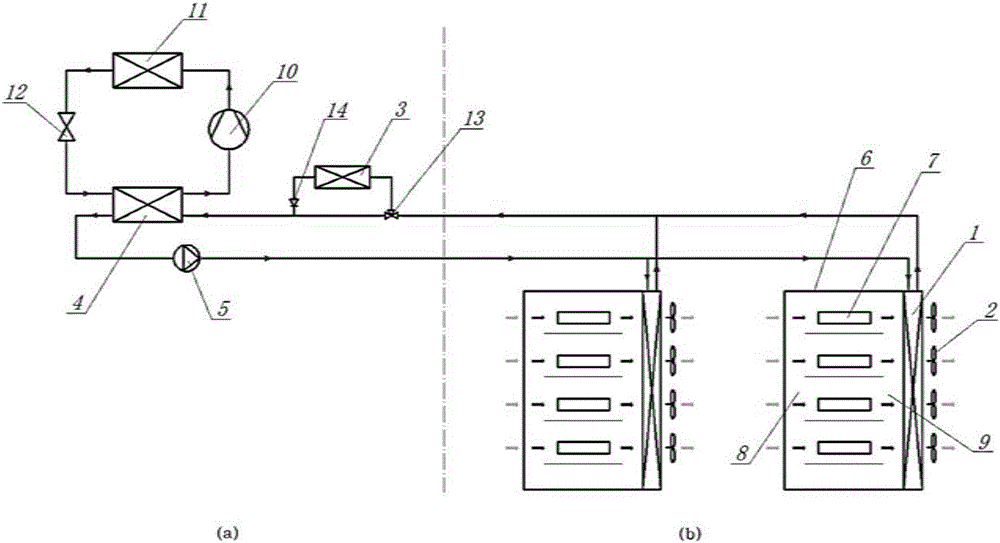
[0019] Such as figure 1 As shown, this embodiment includes: cabinets 6, a heat pipe circulation circuit, and an auxiliary cooling circuit connected in series in sequence.

[0020] Such as figure 1 As shown in (b), the cabinet 6 is provided with a cold air duct 8, a server device 7, and a hot air duct 9 in sequence.

[0021] The front door of the cabinet 6 adopts a mesh door with a high through hole rate.

[0022] The heat pipe circulation loop includes: a heat pipe evaporator back plate 1 and a plate heat exchanger 4 connected in series.

[0023] The height difference between the plate heat exchanger 4 and the heat pipe evaporator back plate 1 is 1.2 to 1.5 m.

[0024] The heat pipe evaporator back plate 1 is a microchannel parallel flow heat exchanger.

[0025] One side of the heat pipe evaporator back plate 1 is connected with the back door of the cabinet 6 and the other side is provided with an evaporation fan 2.

[0026] The evaporation fan 2 is an axial fan.

[002...


PUM


Abstract

The invention provides a heat pipe cooling system for a high-heat density cabinet. The heat pipe cooling system comprises a heat pipe circulation circuit and an auxiliary cooling circuit connected with the heat pipe circulation circuit, wherein the heat pipe circulation circuit comprises a heat pipe evaporator backboard and a plate-type heat exchanger which are connected in series; the vertical height of the plate-type heat exchanger is greater than that of the heat pipe evaporator backboard; the auxiliary cooling circuit comprises the plate-type heat exchanger, a compressor, an external condenser and a throttling device which are sequentially connected in series, or an air-cooled condenser, a three-way valve and a one-way valve; and the heat pipe circulation circuit can be in a multi-split structure form and achieves simultaneous cooling of a plurality of cabinets and a machine room. One set of air conditioning system does not need to be additionally arranged for the machine room, and a bottom cold air supply duct and a top hot air return duct do not need to be arranged, so that the cost is reduced and the energy consumption is reduced.

Description

technical field [0001] The invention relates to a technology in the field of refrigeration systems, in particular to a heat pipe cooling system for high heat density cabinets. Background technique [0002] With the rapid development of IT technology, faster and more powerful high-power density rack servers and network switches are more and more used, and the deployment density of equipment is also increasing, making the energy consumption of a single cabinet And the heat dissipation per unit area rises sharply, which leads to the high heat density phenomenon of local "overheating" of the cabinet. In order to ensure the normal operation of the cabinet equipment and the comfort of the computer room environment, a cooling solution that can meet the cooling requirements of high heat density cabinets is urgently needed. [0003] The traditional computer room cooling system generally adopts the method of separating hot and cold air channels and supplying air from bottom to top to...

Claims


Application Information

Patent Timeline
IPC IPC(8): H05K7/20
Inventor 陈江平朱建民李万勇
Owner SHANGHAI JIAO TONG UNIV
Why Eureka
Try Eureka