Road cross section structure of mountainous road

A construction and highway technology, applied in the field of road section structure of winding mountain highways, can solve the problems of highway overturning downhill cliffs, slab suspension ruptures, and more concrete needs, so as to improve safety and comfort, enhance road bearing capacity, and save concrete. Effect

Active Publication Date: 2017-01-18
NO 2 ENG CO LTD OF CHINA RAILWAY CONSTR 11 BUREAU GRP +1
View PDF5 Cites 4 Cited by
  • Summary
  • Abstract
  • Description
  • Claims
  • Application Information

AI Technical Summary

Problems solved by technology

[0002] The cross-section design of the existing highway pavement is generally a rectangular slab. This design is suitable for vehicles to turn, overtake, and pass vehicles at will. The design form requires more concrete, which is an excessive consumption of materials for rural roads and low-grade roads in mountainous areas with single-lane vehicles; once the slab body breaks or the expansion joint leaks in this slab road, it will quickly lead to substratum lamination Bad slopping, even the board is warped and cracked until it cannot be used
[0003] The use of such rectangular plates on winding mountain roads in mountainous areas is more likely to cause the inner side to scour the mountain, causing landslides, and the outer side to scour slopes and cliffs, causing the plates to hang, crack and subgrade to collapse; wet and slippery rainy days even cause vehicles to slip out of the road and turn down the cliffs

Method used


Image

  • Road cross section structure of mountainous road
  • Road cross section structure of mountainous road
  • Road cross section structure of mountainous road

Examples


Embodiment Construction

[0025] The present invention as figure 1 / 2 / 3 shown.

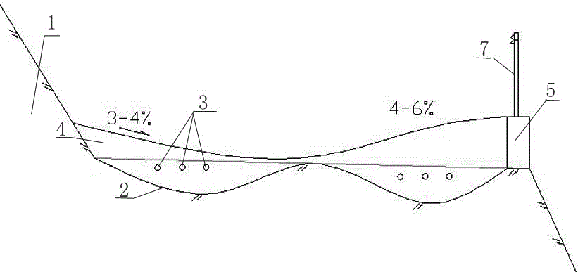
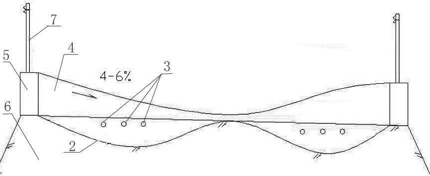
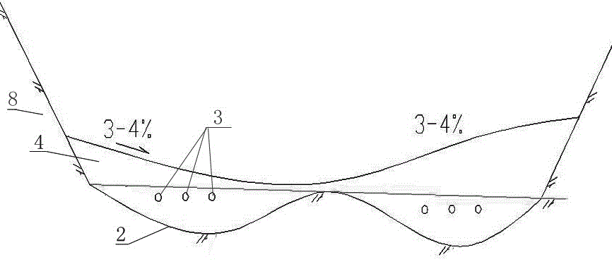
[0026] A road cross-section structure for mountainous roads. The road cross-section structure of mountainous roads includes road grooves. Concrete road surface layer 4 is poured on top, wherein the concrete road surface layer 4 is a streamlined groove-like structure with high concave on both sides, and the pavement base 2 and concrete road surface layer 4 finally form a cross-sectional structure of "∞".

[0027] The "∞" cross-section of the road base 2 and the concrete road surface 4 is constructed in the slope section of the curve, and steel bars 3 are added longitudinally in the concrete road surface 4 to strengthen the strength of the road surface. drain.

[0028] In the mountain road, one side is the hillside side wall, and the other side is the steep slope and steep cliff structure 1, the concrete road surface layer 4 of the hillside side wall is naturally connected with the slope surface, and the rainwater is conve...


PUM


Abstract

The invention discloses a road cross section structure of a mountainous road. A pavement base layer is of a double-wave cross section structure of which the middle part is high and two sides are concave; a concrete road surface layer is cast on the pavement base layer; the top surface of a concrete road is of a streamline groove shaped structure of which two sides are high and the middle part is concave; the pavement base layer and the concrete road surface layer finally form a 'horizontal 8-shaped' cross section structure. The strength of a plate body can be improved by thickening the concrete road surface layer at the bottom of a wheel; due to adoption of ditches in the middle, water can be gathered, so that a soil body is not flashed by the water; due to adoption of a concave transverse slope, a mountain slope side can be prevented from being flashing by surface ponding, and the plate bottom can be prevented from returning flashing, so that a plate can be prevented from being suspended, vehicles can run relatively safely, and a roadbed can be relatively safe; due to adoption of grooves in two sides, the chassis of a vehicle body can be lifted upwards, so that the vehicle body can be protected; as water flowing down from a mountain is gathered on one side or two sides uniformly, original water drainage states of the mountain are not artificially changed, centralized water discharge flashing can be avoided, natural original ecology can be maintained, and a middle water discharge ditch can be clear without sludge.

Description

technical field [0001] The invention relates to the road section structure of mountain roads, especially the road section structure of winding mountain roads in areas with many slopes. Background technique [0002] The cross-section design of the existing highway pavement is generally a rectangular slab. This design is suitable for vehicles to turn, overtake, and pass vehicles at will. The design form requires more concrete, which is an excessive consumption of materials for rural roads and low-grade roads in mountainous areas with single-lane vehicles; once the slab body breaks or the expansion joint leaks in this slab road, it will quickly lead to substratum lamination Bad slopping, even the board body warps and cracks until it cannot be used. [0003] The use of such rectangular plates on winding mountain roads in mountainous areas is more likely to cause the inner side to scour the mountain, causing landslides, and the outer side to scour the slopes, causing the plates ...

Claims


Application Information

Patent Timeline
Patent Type & Authority Applications(China)
IPC IPC(8): E01C1/00E01C3/00
CPCE01C1/002E01C3/00Y02A30/60
Inventor 邹永泉陈红兵刘国雄凌俊东赵凯兵
Owner NO 2 ENG CO LTD OF CHINA RAILWAY CONSTR 11 BUREAU GRP
Why Eureka
Try Eureka