Image processing-based automobile body paint film defect detection and identification method
A defect detection and identification method technology, applied in image data processing, image enhancement, image analysis and other directions, can solve the problem of inaccurate identification of car body paint film defects, and achieve the effect of reducing production cost, improving accuracy and improving quality
- Summary
- Abstract
- Description
- Claims
- Application Information
AI Technical Summary
Problems solved by technology
Method used
Image

Examples
Embodiment Construction
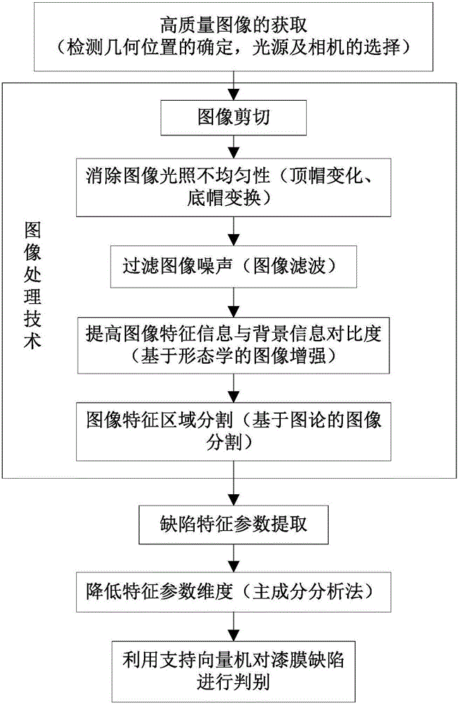
[0055] refer to figure 1 , a method for detecting and identifying vehicle body paint film defects based on image processing, the detecting and identifying method includes the following steps:
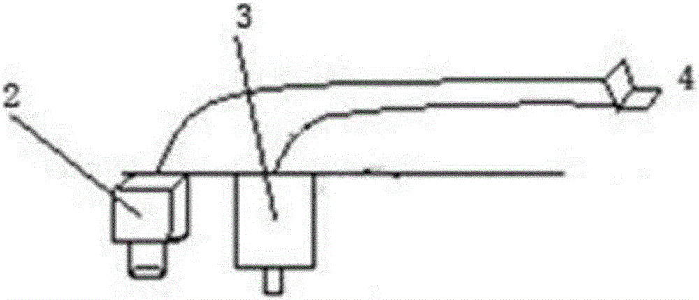
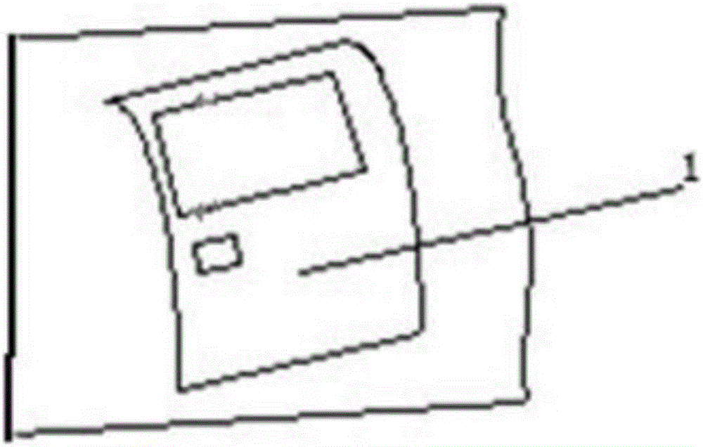
[0056] Step 1, acquire an image; use the laser transmitter 2 in the vehicle body paint film defect detection system to vertically irradiate the surface of the test piece 1 to obtain an image;
[0057] Step 2, image preprocessing; after collecting the defect image of the paint film of the car body, in order to improve the image quality, thereby improving the accuracy and efficiency of defect detection, the image is preprocessed;
[0058] Step 3, extracting the defect characteristic parameters of the car body paint film; selecting the geometric features, grayscale feature values and main horizontal projection feature values of the car body paint film as the defect characteristic parameters;
[0059] Step 4. Reduce the dimension of the characteristic parameters; use the principal comp...
PUM
 Abstract
Description
Claims
Application Information