Method for manufacturing a rotary electric machine rotor

A manufacturing method and technology for rotating electrical machines, which are applied in the manufacture of motor generators, stator/rotor bodies, electromechanical devices, etc., can solve problems such as increased manufacturing costs and decreased productivity, and achieve good productivity and suppress scattering.

Inactive Publication Date: 2017-01-18
TOYOTA JIDOSHA KK
View PDF5 Cites 5 Cited by
  • Summary
  • Abstract
  • Description
  • Claims
  • Application Information

AI Technical Summary

Problems solved by technology

However, the resin is injected in a state where the two magnets are separated toward both sides in the axial direction in the magnet hole, and thus the position of each magnet must be controlled very precisely.
As a result, there is a possibility that productivity decreases and manufacturing costs increase

Method used


Image

  • Method for manufacturing a rotary electric machine rotor
  • Method for manufacturing a rotary electric machine rotor
  • Method for manufacturing a rotary electric machine rotor

Examples


Embodiment Construction

[0018] Embodiments of the present invention will be described below using the drawings. The shapes, materials, and numbers to be described below are merely illustrative and can be appropriately changed in accordance with the specifications of the rotating electric machine. In the case where a plurality of embodiments, modified examples, and the like are provided in the following description, these can be appropriately combined and implemented. In the following description, the same components are denoted by the same reference numerals throughout the drawings. Also, in the description herein, the previously mentioned reference numerals are used where necessary.

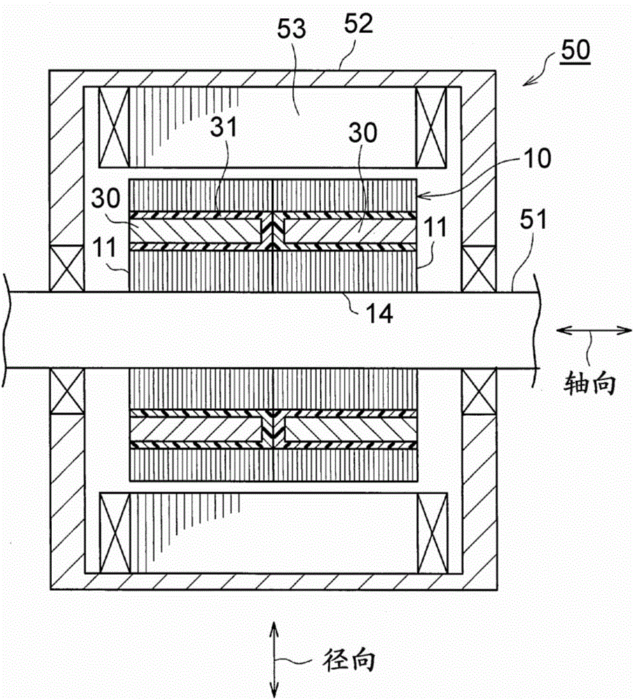
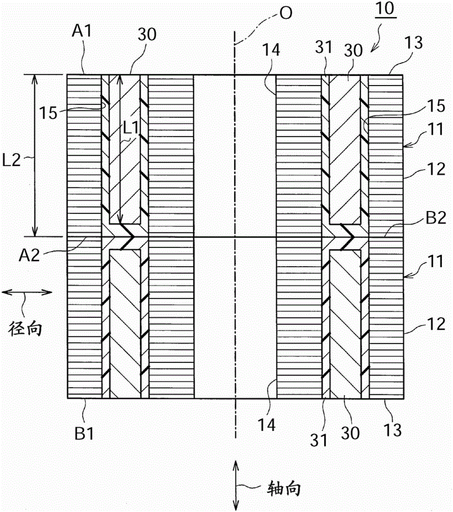
[0019] figure 1 It is a cross-sectional view of a rotating electric machine 50 including a rotating electric machine rotor 10 manufactured by the manufacturing method of the embodiment. figure 2 It is a sectional view of the rotating electric machine rotor 10 manufactured by the manufacturing method of the embodime...


PUM

PropertyMeasurementUnit
thicknessaaaaaaaaaa

Abstract

The invention relates to a method for manufacturing a rotary electric machine rotor. The method for manufacturing the rotary electric machine rotor includes: forming core block elements; inserting magnets in corresponding one of magnet holes; forming magnet core blocks by injecting a molten resin into each of the magnet holes from above the magnet, solidifying the molten resin, and thereby forming a resin portion so as to integrate each of the core block elements and the magnets, the molten resin is injected at a second end surface, and end surfaces of the magnets being exposed on a first end surface; forming the rotary electric machine rotor by stacking and integrating plural magnet core blocks, the plural magnet core blocks being stacked such that the first end surfaces of two magnet core blocks that are disposed at both ends in an axial direction constitute end surfaces at both ends of the rotary electric machine rotor in the axial direction.

Description

technical field [0001] The present invention relates to a method of manufacturing a rotor for a rotating electrical machine comprising a magnet core and a plurality of magnet cores integrated therein by integrating magnets and core elements made of magnetic material formed. Background technique [0002] Generally, there is known a configuration of a rotor of a rotating electrical machine using a rotor core made of a magnetic material. There is also known a rotor in which magnet holes penetrating in the axial direction are formed at a plurality of positions in the circumferential direction of the rotor core and magnets are arranged in the respective magnet holes. In order to reduce the iron loss of the magnets, there are cases where the magnets arranged at a plurality of circumferential positions in this configuration are each separately arranged as a plurality of magnets in the axial direction of the rotor. [0003] In Japanese Patent Application Publication No. 2007-28235...

Claims


Application Information

Patent Timeline
Patent Type & Authority Applications(China)
IPC IPC(8): H02K1/28H02K15/02
CPCH02K1/28H02K15/02H02K1/276H02K2213/12H02K15/03H02K1/04H02K1/27H02K15/12
Inventor 服部宏之
Owner TOYOTA JIDOSHA KK
Why Eureka
Try Eureka