Virtual viewpoint video quality evaluation method

A technology of video quality and evaluation method, which is applied in the field of virtual viewpoint video quality evaluation, and can solve the problems of not considering the temporal flicker distortion of virtual viewpoint video, insufficient calculation, and only considering the distortion of the drawing process, etc.

Active Publication Date: 2017-01-18
SHENZHEN INST OF ADVANCED TECH CHINESE ACAD OF SCI
View PDF8 Cites 13 Cited by
  • Summary
  • Abstract
  • Description
  • Claims
  • Application Information

AI Technical Summary

Problems solved by technology

[0009] The above-mentioned virtual viewpoint video quality evaluation scheme has the following disadvantages: the temporal flicker distortion in the virtual viewpoint video is not considered
However, the existing v...

Method used


Image

  • Virtual viewpoint video quality evaluation method
  • Virtual viewpoint video quality evaluation method
  • Virtual viewpoint video quality evaluation method

Examples


Embodiment 1

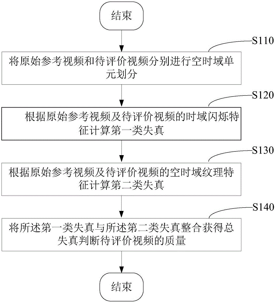
[0056] A method for evaluating video quality from a virtual viewpoint, comprising the following steps:

[0057] Step S110, divide the original reference video and the video to be evaluated into space-time domain units respectively.

[0058] Step S110 includes:

[0059] ① Divide the original reference video and the video to be evaluated into several image groups consisting of several consecutive frames in the temporal domain.

[0060] ② Each image in the image group is divided into several image blocks, and the continuous image blocks in the time domain form space-time domain units.

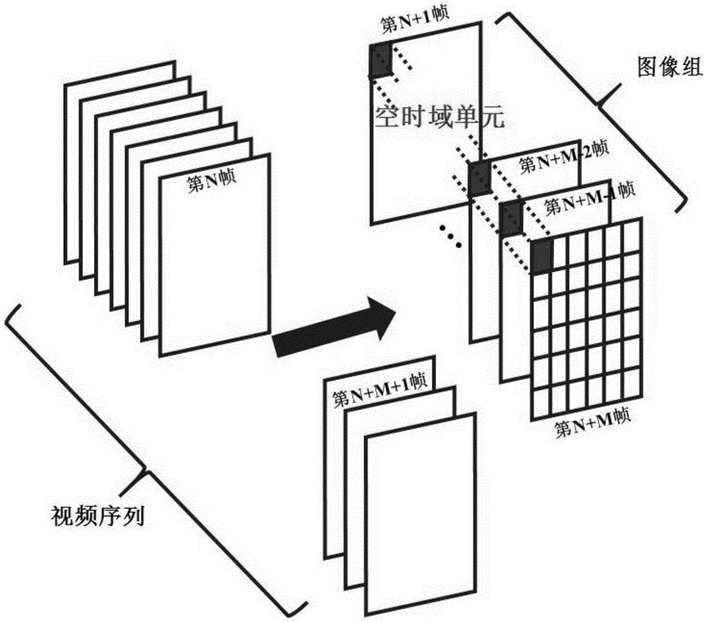
[0061] In this embodiment, the space-time domain unit is composed of several time-domain continuous image blocks with the same spatial position.

[0062] Specifically, it is first necessary to divide the original reference video and the video to be evaluated into space-time domain units, and the schematic diagram of the process is as follows figure 2 shown. The video sequence (the original re...

Embodiment 2

[0121] Step S110, divide the original reference video and the video to be evaluated into space-time domain units respectively.

[0122] Step S110 includes:

[0123] ① Divide the original reference video and the video to be evaluated into several image groups consisting of several consecutive frames in the temporal domain.

[0124] ② Each image in the image group is divided into several image blocks, and the continuous image blocks in the time domain form space-time domain units.

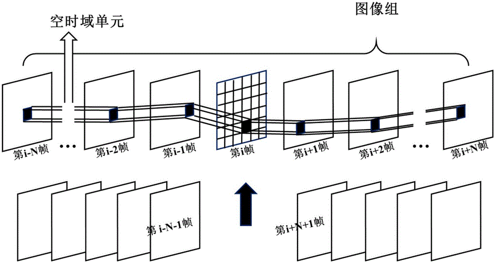
[0125] The space-time domain unit is composed of several time-domain continuous image blocks with different space-domain positions describing the motion trajectory of the same object.

[0126] Specifically, it is first necessary to divide the original reference video and the video to be evaluated into space-time domain units, and the schematic diagram of the process is as follows image 3 shown. The video sequence (the original reference video and the video to be evaluated) is divided into several...


PUM


Abstract

The invention relates to a virtual viewpoint video quality evaluation method. According to the invention, time domain blink distortion of virtual viewpoint video is calculated by taking all pixels in a space-time domain unit as a unit, so that erroneous estimation which is brought about by a pixel-to-pixel time domain blink distortion calculation mode for virtual viewpoint video human eye perception distortion is avoided. The virtual viewpoint video quality evaluation method not only considers distortion brought about by a depth image error but also considers distortion introduced by left and right viewpoint texture images when performing calculation on the time domain blink distortion of the virtual viewpoint video. The virtual viewpoint video quality evaluation method can effectively evaluate the time domain blink distortion which imposes great influences on the subjective quality in the virtual viewpoint video, thereby more conforming to a result of human eye subjective perception when the virtual viewpoint video quality is evaluated, and enabling virtual viewpoint video quality evaluation to be more accurate and more comprehensive.

Description

technical field [0001] The invention relates to video quality evaluation technology, in particular to an accurate and comprehensive virtual viewpoint video quality evaluation method. Background technique [0002] With the development of 3D video technology, more and more movies and TV programs are shot using 3D technology, and various 3D displays and 3D TVs are gradually becoming popular. It is foreseeable that 3D video will become the mainstream in the future. [0003] At present, the international standards organization MPEG (Moving Picture Experts Group, Motion Picture Experts Group) and ITU-T VCEG (International Telecommunication Union-Telecommunication Standardization Sector Video Coding Experts Group, International Telecommunication Union Communication Standardization Organization Video Coding Experts Group) have jointly formulated a depth information-based 3D video coding standard. In this standard 3D video solution, the encoder only needs to encode and transmit 2 to...

Claims


Application Information

Patent Timeline
IPC IPC(8): H04N17/00H04N19/154
Inventor 张云刘祥凯
Owner SHENZHEN INST OF ADVANCED TECH CHINESE ACAD OF SCI
Why Eureka
Try Eureka