

Engine pyrotechnics starting system
A starting system and engine technology, applied in the direction of machines/engines, mechanical equipment, gas turbine devices, etc., can solve the problems of low reliability of missile engines, inability to meet the rapid response of missiles, low efficiency, etc., and achieve the effect of improving sealing
Inactive Publication Date: 2013-12-11
HARBIN DONGAN ENGINE GRP
View PDF0 Cites 7 Cited by
- Summary
- Abstract
- Description
- Claims
- Application Information
AI Technical Summary
Problems solved by technology
The ignition system uses a coil and an ignition nozzle. In most cases, the starting fuel needs to be ignited first, and the small torch formed thereby ignites the main fuel. This type of ignition is relatively low reliability for bomb engines.
For small turbofan engines, the above-mentioned auxiliary engines are large in size, low in efficiency, long in engine start-up time, and relatively high in cost, which cannot meet the rapid response and reliable maneuverability requirements of missiles as weapons and equipment.
Method used
View moreImage
Smart ImageViewing Examples

Examples
Embodiment 1
Login to View More PUM
 Abstract
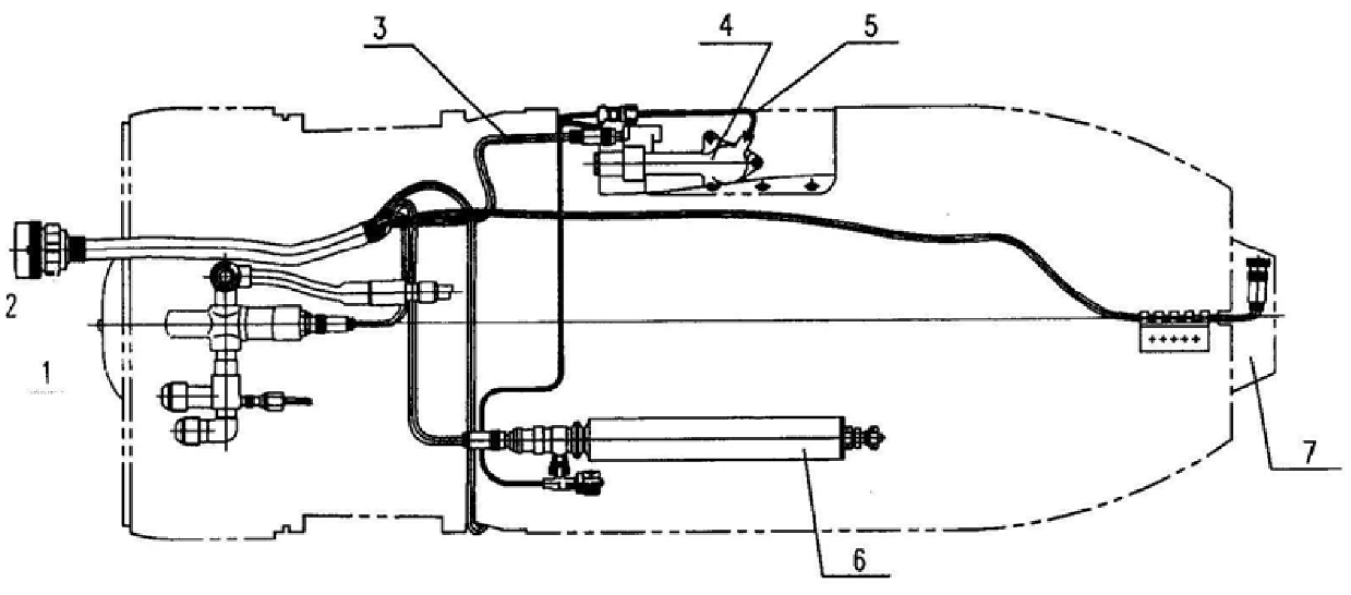
The invention relates to an engine pyrotechnic starting system, which includes an engine oil supply pipe, an oxygen bottle, a pyrotechnic igniter, and a pyrotechnic starter. The pyrotechnic igniter is installed on the combustion chamber, and the pyrotechnic starter is installed at the tail of the engine. , the fuel supply pipe of the engine, the pyrotechnic igniter, the pyrotechnic starter and the gas outlet of the oxygen cylinder are equipped with electric detonators and are all connected to the external integrated controller, and one end of the fuel supply pipe is connected to the external fuel oil The other end is connected with the nozzle of the combustion chamber of the engine, and the oxygen cylinder is connected with the pyrotechnic igniter through the oxygen supplement pipe. Valves are also arranged at the electric initiator at the inside and at the gas outlet of the oxygen cylinder. The invention has the characteristics of simple structure, high starting success rate and reduced engine weight, can directly ignite the auxiliary fuel oil of the engine, and at the same time use an oxygen bottle to ignite and replenish oxygen, thereby shortening the ignition time of the engine.
Description
Engine pyrotechnics starting system technical field The invention relates to a starting system, in particular to an engine pyrotechnic product starting system. Background technique At present, the vast majority of aero-engines use starter motors to rotate, fuel solenoid valves are turned on to supply fuel, and electric ignition coils are ignited. The starter motor is used to turn the engine turbine, the ground start can use the power vehicle, and the air start can only use the battery. The ignition system uses a coil and an ignition nozzle. In most cases, the starting fuel needs to be ignited first, and then the main fuel is ignited by the resulting small torch. This ignition form is relatively low reliability for bomb engines. For small turbofan engines, the above-mentioned auxiliary engines are large in size, low in efficiency, long in engine start-up time, and relatively high in cost, which cannot meet the requirements of rapid response and reliable maneuverability of ...
Claims
Login to View More Application Information
Patent Timeline
 Patent Type & AuthorityPatents(China)
IPC IPC(8): F02C7/272
Inventor王学斌石光张玉宝杨宇斌王智宇
OwnerHARBIN DONGAN ENGINE GRP