Automatic injection-molding part runner cutting equipment

A technology for injection molded parts and water cutouts, which is applied in the field of automatic water cutout equipment for injection molded parts. It can solve the problems of low efficiency, damage to the workpiece, time-consuming and labor-intensive problems, so as to reduce labor intensity, ensure the accuracy of positioning, and operate simply and conveniently. Effect

Inactive Publication Date: 2017-01-25
GREE ELECTRIC APPLIANCES INC
View PDF3 Cites 13 Cited by
  • Summary
  • Abstract
  • Description
  • Claims
  • Application Information

AI Technical Summary

Problems solved by technology

In the injection molding workshop of the prior art, the runners are generally cut off manually with scissors, and each injection molded part needs to be cut many times, which is time-consuming, labor-intensive, and inefficient
[0004] Taking the rice cooker switch button as an example, each injection molded part is injected with 16 switch parts at one time, and the normal separation of the nozzle needs to be cut 16 times, and because the nozzle is large, it needs to be flattened with a knife after cutting, and the cutting and knife batch process It is easy to scratch the workpiece and hurt the hand, the efficiency is low, and the defect rate is high

Method used


Image

  • Automatic injection-molding part runner cutting equipment
  • Automatic injection-molding part runner cutting equipment

Examples


Embodiment 1

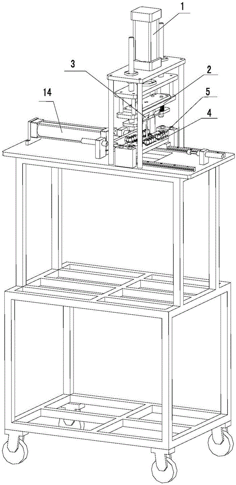
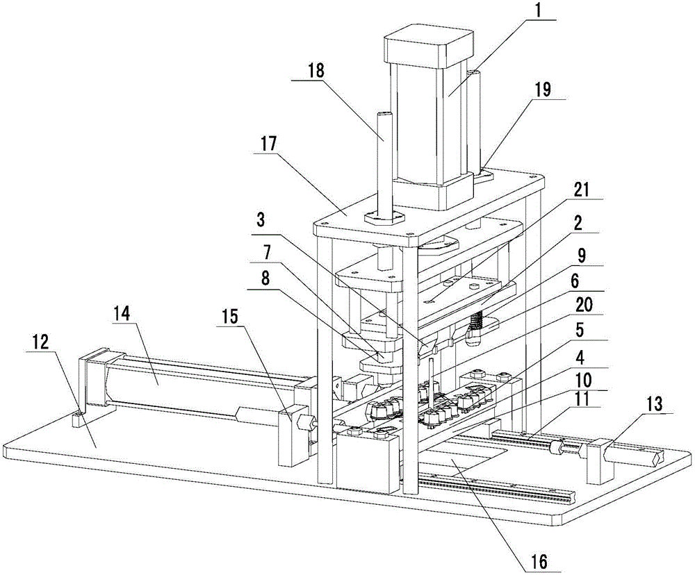
[0024] The invention provides an automatic water cutting device for injection molded parts, such as Figure 1-2 As shown, it includes: an upper mold that can move up and down under the drive of the first cylinder 1 and a lower mold that cooperates with the upper mold. The upper mold includes a pressing plate 2 and a cutting knife 3 arranged below the pressing plate 2. The lower mold It includes a bottom plate 4 and a bottom punch 5 fixedly connected to the bottom plate 4 for fixing the injection molded part. The shape of the cutting knife 3 is adapted to the outer contour of the part to be cut on the injection molded part.

[0025] Driven by the driving shaft of the first cylinder 1, the upper mold is cut from top to bottom along the outer contour of the part to be cut on the injection molded part, and the flow channel part of the injection molded part is completely peeled off at one time, and cut off by the first cylinder. The knife separation nozzle replaces the manual separ...


PUM


Abstract

The invention relates to the technical field of cutting of injection-molding parts, in particular to automatic injection-molding part runner cutting equipment which comprises an upper die and a lower die. The upper die is driven to moving up and down by a first cylinder, and the lower die is matched with the upper die. The upper die comprises a clamp plate and a cutting blade arranged under the clamp plate; the lower die comprises a bottom plate and a bottom punch which is fixedly connected to the bottom plate and used for fixing an injection-molding part; the shape of the cutting blade is matched with the profile of a to-be-cut portion of the injection-molding part. With the matching structure of the upper die and the lower die, the upper die is driven to move from bottom to top to cut along the profile of the to-be-cut portion of the injection-molding part under driving of the first cylinder, so that the runner portion of the injection-molding part is peeled off completely at one step; the process of separating runners by the cutting blade under driving of the first cylinder substitutes for the process of manual separation of runners, contact between the cutting blade and the hands is avoided during the whole operating process so that workers' hands are protected; besides, the equipment is easy and convenient to operate and reduces labor intensity of workers.

Description

technical field [0001] The invention relates to the technical field of cutting injection molding parts, in particular to an automatic water cutting device for injection molding parts. Background technique [0002] Injection molded parts refer to various injection molded products produced by injection molding machines, collectively referred to as injection molded parts, including various packaging, parts, etc. It is mainly made of materials such as polyethylene or polypropylene with various organic solvents added. After the plastic is plasticized in the heating barrel of the injection molding machine, it is injected into the cavity of the closed mold by the plunger or the reciprocating screw to form the plastic processing method of the product. This method can process products with complex shapes, precise dimensions or inserts, and has high production efficiency. Most thermoplastics and some thermosetting plastics (such as phenolic plastics) can be processed by this method....

Claims


Application Information

Patent Timeline
Patent Type & Authority Applications(China)
IPC IPC(8): B29C45/38
CPCB29C45/38
Inventor 刘群马栋陈国强江祥林
Owner GREE ELECTRIC APPLIANCES INC
Why Eureka
Try Eureka