Side-wall structure of railway vehicle

A technology for the side walls and side walls of rail vehicles, which is applied in the direction of railway car body, railway car body parts, transportation and packaging, etc. The effect of easy disassembly

Active Publication Date: 2017-01-25
ZHUZHOU ELECTRIC LOCOMOTIVE CO LTD
View PDF6 Cites 3 Cited by
  • Summary
  • Abstract
  • Description
  • Claims
  • Application Information

AI Technical Summary

Problems solved by technology

However, this kind of movable side wall has two obvious limitations: one is that the bearing capacity of this kind of movable side wall is very weak, and it can hardly withstand the longitudinal force of the locomotive
The second is that the original intention of the design of the movable side wall is also to facilitate the installation, maintenance and repair of the equipment in the mechanical room. However, since only half of the width of the side wall can be opened, the mechanical room equipment on the side of the fixed side wall is still not easy to install, maintain and repair.

Method used


Image

  • Side-wall structure of railway vehicle
  • Side-wall structure of railway vehicle
  • Side-wall structure of railway vehicle

Examples


Embodiment Construction

[0040] The present invention will be described in detail below with reference to the accompanying drawings and examples. It should be noted that, in the case of no conflict, the embodiments of the present invention and the features in the embodiments can be combined with each other. For the convenience of description, if the words "up", "down", "left" and "right" appear in the following, it only means that the directions of up, down, left and right are consistent with the drawings themselves, and do not limit the structure.

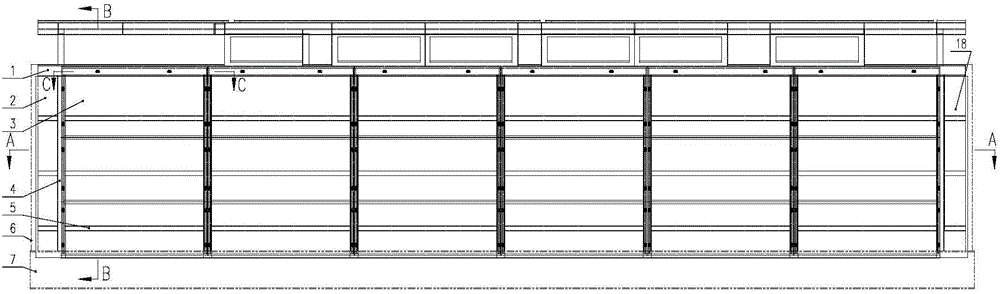
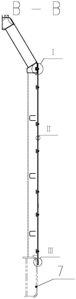
[0041] A rail vehicle side wall structure locomotive side wall structure, such as figure 1As shown, it is mainly composed of side wall skeleton, side wall movable skin 3, longitudinal flat plate 16, longitudinal vertical plate 15, sealing strip 8, sealing strip 14, sealing strip 17, etc., wherein the side wall skeleton is composed of side wall string girder 1, The side wall fixed skin 2, the side wall column 4, the side wall beam 5, the nut seat 9, the s...


PUM


Abstract

The invention discloses a side-wall structure of a railway vehicle. The side-wall structure comprises a side-wall skeleton, wherein the side-wall skeleton is used for being fixed on a bottom-frame boundary beam, and comprises a plurality of side-wall vertical columns, a plurality of intermediate longitudinal beams and a side-wall upper-chord beam; a side-wall fixing skin is respectively arranged between the vertical column at the front end part of the side wall and a wall-partitioning vertical column of a driver cab and between the vertical column at the rear end part of the side wall and a vertical column of the rear-end wall; and detachable side-wall movable skins are arranged in the area enclosed by the vertical column at the front end part of the side wall, the vertical column at the rear end part of the side wall, the side-wall upper-chord beam and the bottom-frame boundary beam. The side-wall structure disclosed by the invention has the advantages that the side-wall skeleton is assembled and welded on the bottom-frame boundary beam, so that the welding can be carried out on welding seams between the side-wall vertical columns and the bottom-frame boundary beam outside a vehicle body. In addition, great convenience is brought for installation, overhauling and maintenance of equipment in a machine room.

Description

technical field [0001] The invention relates to a rail vehicle side wall structure, belonging to the field of rail vehicle bodies. Background technique [0002] The machinery room is the space where the locomotive installs and integrates various on-board equipment. Therefore, the machinery room needs to be sealed to prevent rain and snow from drifting in. The mechanical room is a closed space composed of the underframe, the partition wall of the driver's cab, the rear end wall, the left and right side walls and the top cover, in which the underframe, the partition wall of the cab, the rear end wall, the left and right side walls are welded together , the top cover and other components are connected by bolts. [0003] The traditional side wall of a locomotive is a fixed welded structure that is welded together by columns, beams, upper chord beams, the upper structure of the side wall and the skin. The shielding of the equipment installation framework above the chassis leads...

Claims


Application Information

Patent Timeline
Patent Type & Authority Applications(China)
IPC IPC(8): B61D17/08
CPCB61D17/08
Inventor 黄学君蒋忠城何安清金希红
Owner ZHUZHOU ELECTRIC LOCOMOTIVE CO LTD
Why Eureka
Try Eureka