
Apparatus for the melt spinning and cooling of filament family

A filament bundle and spinning technology, applied in textiles and papermaking, filament/thread forming, fiber processing, etc., can solve the problems of flow resistance and uneven cold air delivery, and achieve the effect of improving performance and avoiding rapid cooling

Active Publication Date: 2017-01-25
OERLIKON TEXTILE GMBH & CO KG
View PDF4 Cites 4 Cited by
  • Summary
  • Abstract
  • Description
  • Claims
  • Application Information

AI Technical Summary

Problems solved by technology

However, there are still different flow resistances passing through the filament bundle between the upper and lower regions of the cooling shaft and the consequent uneven effect of conveying cold air

Method used


Image

  • Apparatus for the melt spinning and cooling of filament family
  • Apparatus for the melt spinning and cooling of filament family
  • Apparatus for the melt spinning and cooling of filament family

Examples


Embodiment Construction

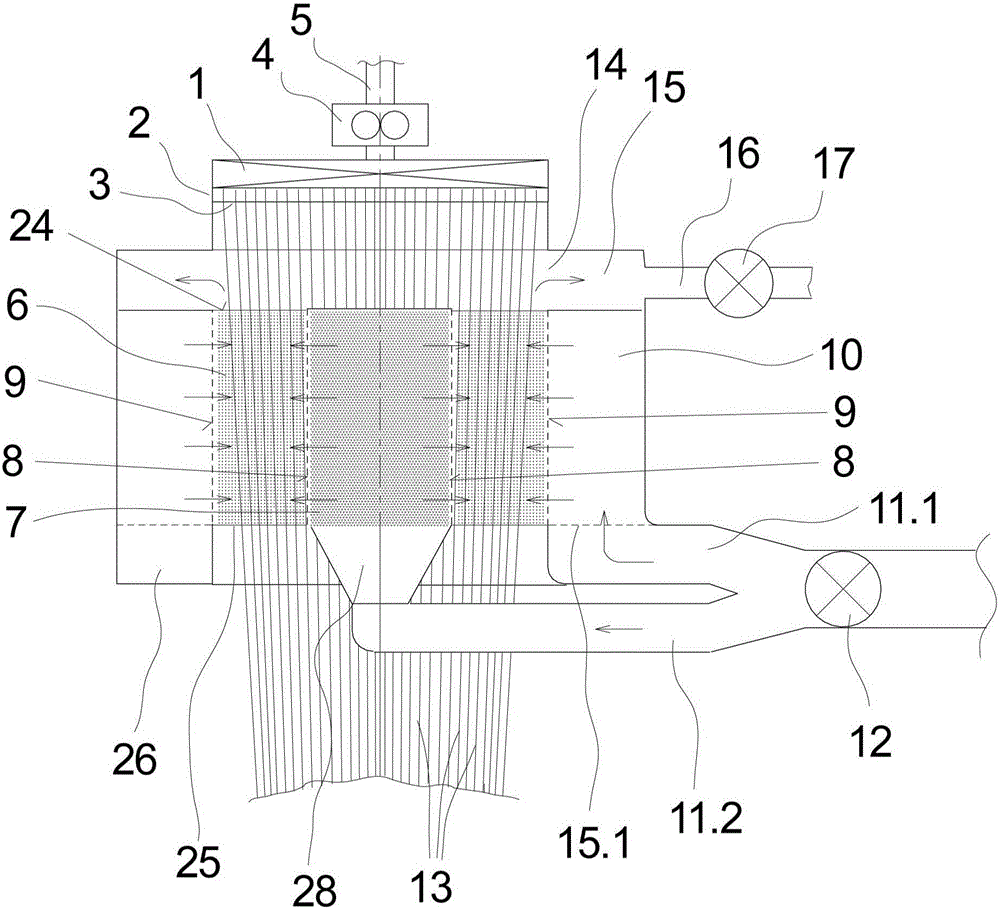
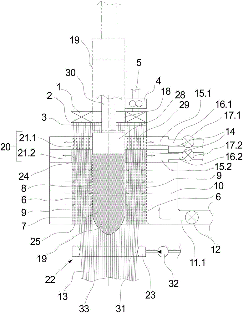
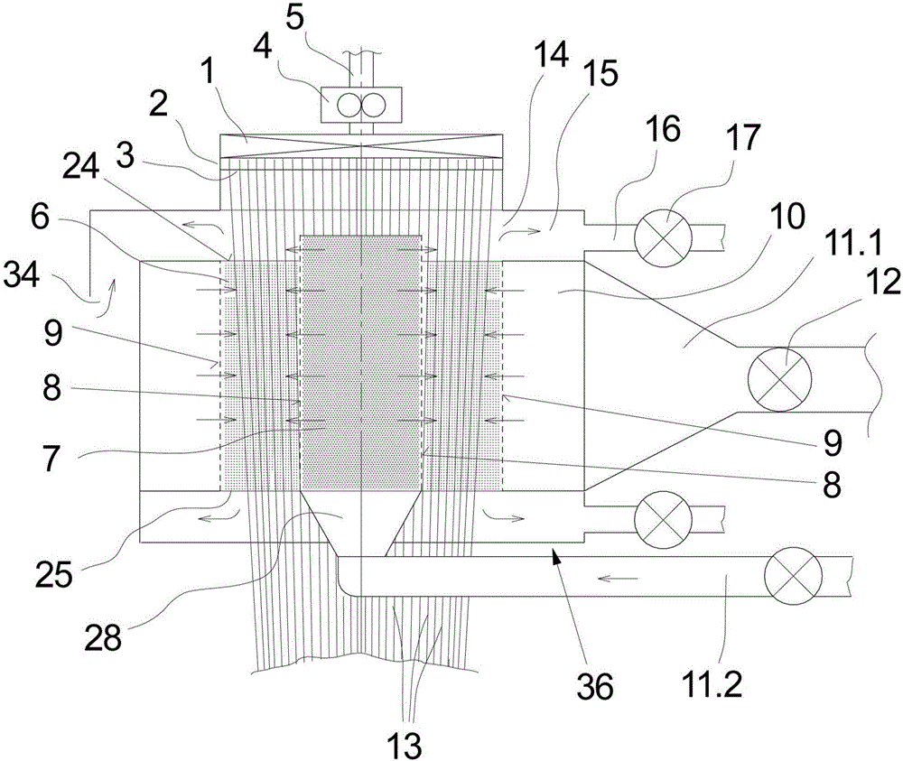
[0027] exist figure 1 A first embodiment of the device for melt-spinning and cooling filament bundles according to the invention is schematically shown in longitudinal section. In this case, only the inventive components essential to the invention are shown schematically.

[0028] This embodiment has a spinning nozzle 1 which on its underside comprises a nozzle plate 2 having a plurality of spinning holes 3 arranged in a ring. The spinning nozzle 1 is connected to a spinning pump 4 which is connected via a melt supply 5 to a melt source (not shown here).

[0029] The spinning nozzle 1 and the spinning pump 4 are usually installed in a heated spinning box. Here, the spinning nozzle 1 is held on the spin beam floor.

[0030] Below the spinning nozzle 1 , an annular cooling tunnel 6 is formed coaxially to the spinning nozzle 1 in such a way that the filament strands extruded through the spinneret openings 3 of the nozzle plate 2 can pass through the cooling tunnel 6 without co...


PUM


Abstract

A device for the melt spinning and cooling of a filament family with an annular spinning nozzle is described. Below the spinneret is formed an annular cooling well between an air-permeable inner wall and an air-permeable outer wall. The inner wall delimits an inner air chamber and the outer wall is assigned to an outer air chamber, the air chambers being at least connectable to a source of cooling air, so that radial cooling air streams can be generated. In order to obtain no turbulence flows, in particular, in the upper region at the inlet of the filaments, an outer suction opening, which opens into a suction chamber, is formed at an inlet of the cooling shaft below the spinning nozzle, the suction chamber being connectable to a vacuum source. It is thus advantageously possible to achieve a regulation of the cooling air flow in the upper region of the cooling shaft.

Description

technical field [0001] This invention relates to apparatus for melt spinning and cooling filament bundles. Background technique [0002] In the melt spinning of synthetic fiber bundles or yarns, many fine filaments are extruded through the spinneret holes of the spinning nozzle. For this purpose, the spinning nozzle is supplied with molten polymer under high pressure. To form a fiber bundle or a plurality of filaments, a number of rod-shaped filaments are assembled or gathered in bundles. Before converging, the filaments are cooled by a cold air flow, so that the melt flow state of the filaments is converted into a solidified state after leaving the spinneret orifice. Uniform cooling of all filaments is of great interest for filament bundle or yarn quality. It is therefore known, in particular for staple fiber production, to feed a plurality of freshly extruded filaments into an annular cooling tunnel in which an external cooling air flow acts on the filament bundle. Suc...

Claims


Application Information

Patent Timeline
Patent Type & Authority Applications(China)
IPC IPC(8): D01D5/092
CPCD01D5/092
Inventor T·罗伊特G·舒特T·瓦拉J·诺伊曼-罗德基尔希
Owner OERLIKON TEXTILE GMBH & CO KG
Learn More