A prefabricated concrete slab-column node and its connection method

A technology of prefabricated concrete slabs and precast concrete, which is applied in the direction of construction and building construction, which can solve the problems of complex steel structure, slow construction speed, and poor economy, and achieve the effects of saving formwork, improving construction efficiency, and simplifying construction technology

Active Publication Date: 2018-10-09
HARBIN INST OF TECH
View PDF5 Cites 0 Cited by
  • Summary
  • Abstract
  • Description
  • Claims
  • Application Information

AI Technical Summary

Problems solved by technology

[0003] In order to solve the problems of complex steel bar structure, difficult pouring, slow construction speed and poor economy in the existing slab-column joint area, the present invention further proposes a prefabricated concrete slab-column joint and its connection method

Method used


Image

  • A prefabricated concrete slab-column node and its connection method
  • A prefabricated concrete slab-column node and its connection method
  • A prefabricated concrete slab-column node and its connection method

Examples


specific Embodiment approach 1

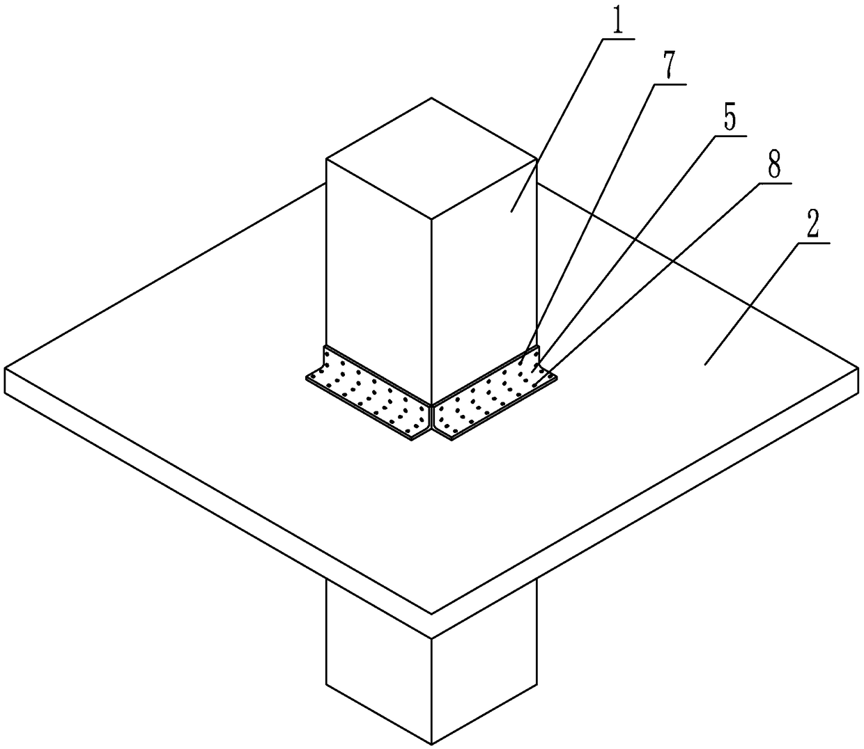
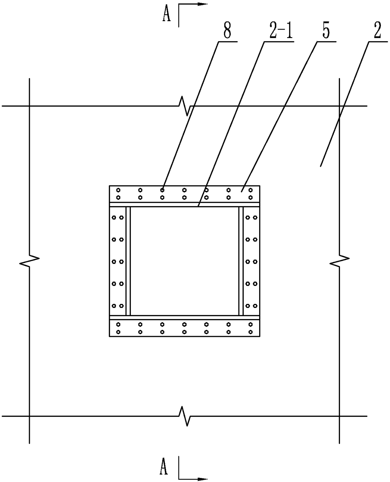
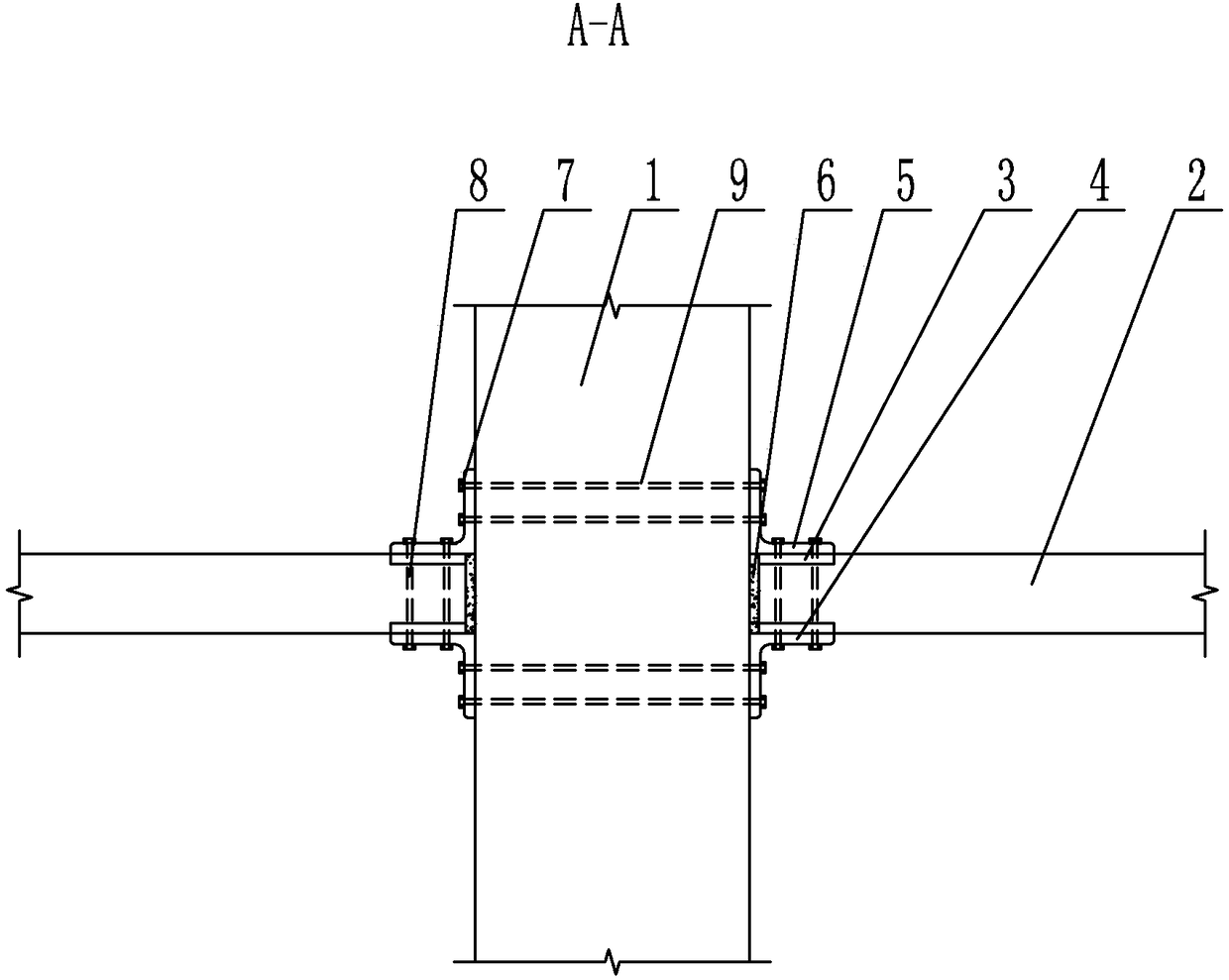
[0014] Specific implementation mode one: combine Figure 1 to Figure 3 To illustrate this embodiment, a precast concrete slab-column node described in this embodiment includes a precast concrete column 1, a precast concrete slab 2, four lower support angle steels 4 and four upper end fixed angle steels 5, and the middle part of the precast concrete slab 2 is provided with Rectangular through hole 2-1, prefabricated concrete column 1 is vertically inserted in rectangular through hole 2-1, and the four side walls of precast concrete column 1 are provided with a lower end support angle steel 4 and an upper end fixed angle steel 5, each One end of the lower support angle steel 4 and the upper end fixed angle steel 5 is fixed on the side wall of the precast concrete column 1, the other end of each lower support angle steel 4 is fixed on the lower end surface of the precast concrete slab 2, and each upper end fixed angle steel 5 The other end is fixedly connected to the upper end su...

specific Embodiment approach 2

[0016] Specific implementation mode two: combination Figure 1 to Figure 3 To illustrate this embodiment, a precast concrete slab-column joint described in this embodiment also includes a plurality of column-through bolts 7 and a plurality of plate-through bolts 8, and the two opposite lower end support angle steels 4 are fixed between the two opposite upper ends. The angle steels 5 are respectively connected by a plurality of through-bolts 7 , and the lower support angle steel 4 and the upper end fixed angle steel 5 on each side are respectively connected by a plurality of through-plate bolts 8 . The undisclosed technical features in this embodiment are the same as those in the first embodiment.

[0017] In such a design, one end of the lower supporting angle steel 4 and the upper fixed angle steel 5 is fixed on the precast concrete column 1 through a plurality of column-through bolts 7 , and the other end of the lower supporting angle steel 4 and the upper fixed angle steel ...

specific Embodiment approach 3

[0018] Specific implementation mode three: combination Figure 1 to Figure 3 To illustrate this embodiment, four embedded steel plates 3 are arranged on the upper and lower end faces of the precast concrete slab 2 described in this embodiment. The embedded steel plates 3 are arranged on the edge of the rectangular through hole 2-1, and the lower end supports the other end of the angle steel 4 It is affixed to the embedded steel plate 3 on the lower end surface of the precast concrete slab 2 , and the other end of each fixed angle steel 5 at the upper end is affixed to the embedded steel plate 3 on the upper end surface of the precast concrete slab 2 . The undisclosed technical features in this embodiment are the same as those in the first or second specific embodiment.

[0019] In this design, the embedded steel plates 3 are arranged at the upper and lower ends of the precast concrete slab 2, so that the fixed angle steel 5 at the upper end and the supporting angle steel 4 at ...


PUM


Abstract

The invention discloses a precast concrete slab column node and a connecting method thereof, and relates to the field of civil engineering. The precast concrete slab column node solves the problems of poor economic performance, low construction speed, casting difficulty and complicated steel bar structures in the existing slab column node region. The slab column node comprises a precast concrete column, a precast concrete slab, four pieces of lower end support angle steel and four pieces of upper end fixing angle steel, wherein a rectangular through hole is formed in the middle part of the precast concrete slab; the precast concrete column is inserted and arranged in the rectangular through hole; one piece of lower end support angle steel and one piece of upper end fixing angle steel are arranged on the side wall of the precast concrete column; one end of each piece of lower end support angle steel and one end of each piece of upper end fixing angle steel are fixedly connected onto the side wall of the precast concrete column; the other end of each piece of lower end support angle steel is fixedly connected onto the lower end surface of the precast concrete slab; the other end of each piece of upper end fixing angle steel is fixedly connected onto the upper end surface of the precast concrete slab. The connecting method comprises the steps of positioning installation; precast concrete slab positioning; precast concrete slab fixation. The precast concrete slab column node and the connecting method are used for forming a precast slab column structure.

Description

technical field [0001] The invention relates to a prefabricated concrete slab-column joint and a connection method thereof. Background technique [0002] The space of the slab-column structure is unobstructed and concise, and the plane layout is flexible, which realizes no beams in the room, and is suitable for multi-high-rise civil buildings and industrial buildings such as factories and warehouses. At present, in the cast-in-place concrete slab-column structure, the joint area where the slab and column intersect should have sufficient bending, shear and punching resistance. The steel reinforcement structure in the joint area is complex and densely arranged, which often makes concrete pouring difficult. It is not conducive to ensuring the quality of structural concrete, and the construction speed is slow; a large number of formwork and supports are required in the construction process of cast-in-place concrete slab-column structures, and the reuse rate is low, resulting in ...

Claims


Application Information

Patent Timeline
Patent Type & Authority Patents(China)
IPC IPC(8): E04B1/20E04B1/21E04B1/38
CPCE04B1/20E04B1/21E04B1/38
Inventor 郑文忠周威侯晓萌王英
Owner HARBIN INST OF TECH
Why Eureka
Try Eureka