Methods and systems for boost control

A technology of supercharging pressure and supercharging engine, which is applied in electrical control, engine control, fuel injection control, etc., and can solve the problems of reduced vehicle drivability and reduced driving experience of vehicle operators.

Active Publication Date: 2017-01-25
FORD GLOBAL TECH LLC
View PDF3 Cites 5 Cited by
  • Summary
  • Abstract
  • Description
  • Claims
  • Application Information

AI Technical Summary

Problems solved by technology

However, a drop in boost output below the driver demanded boost pressure can result in a significant under-delivery of torque demand, and a reduction in vehicle drivability
Additionally, the driving experience for the vehicle operator is reduced

Method used


Image

  • Methods and systems for boost control
  • Methods and systems for boost control
  • Methods and systems for boost control

Examples


Embodiment Construction

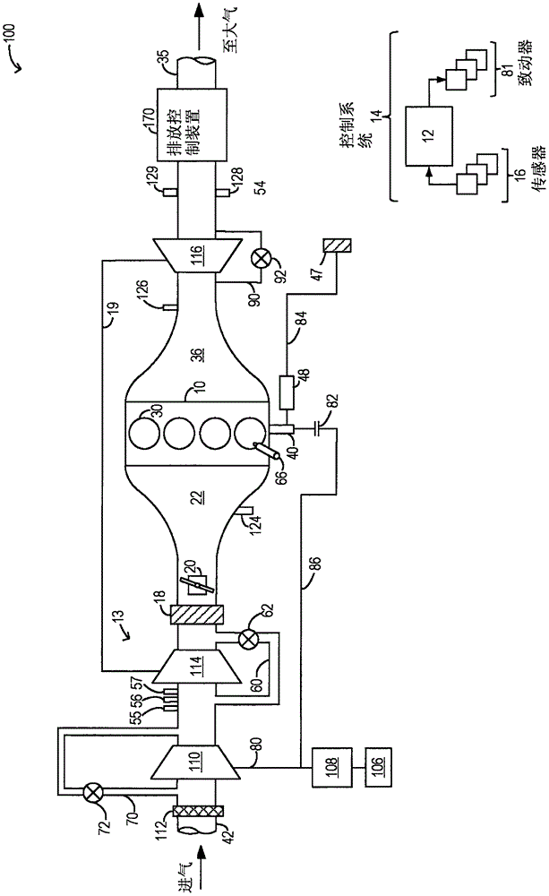
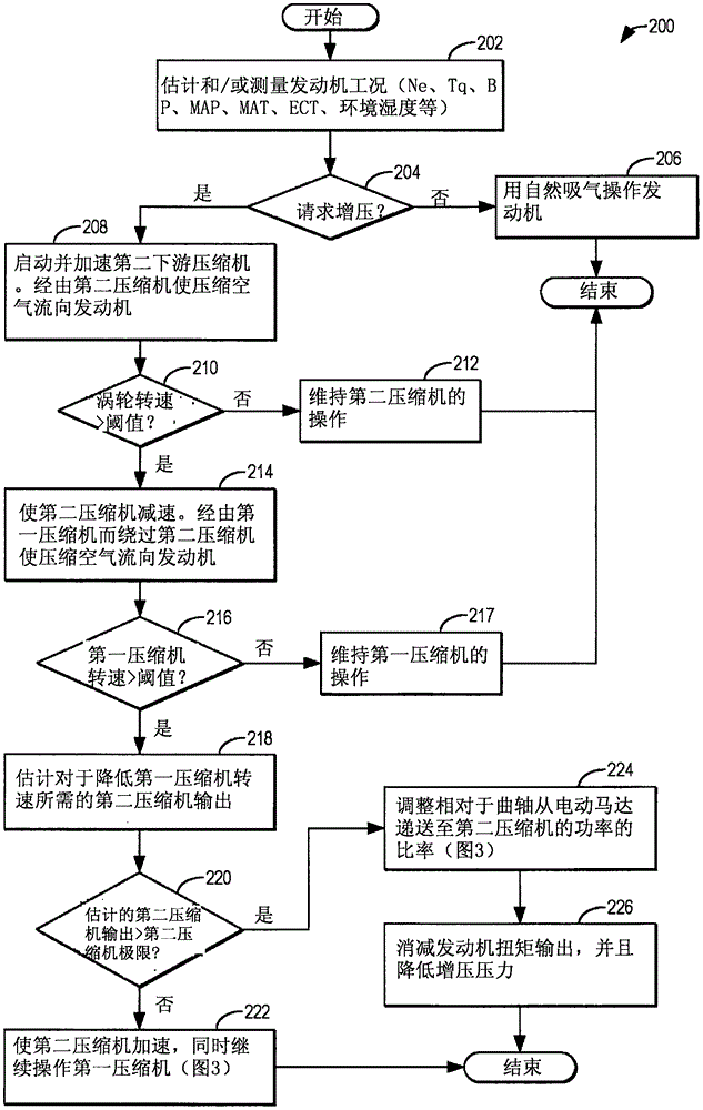
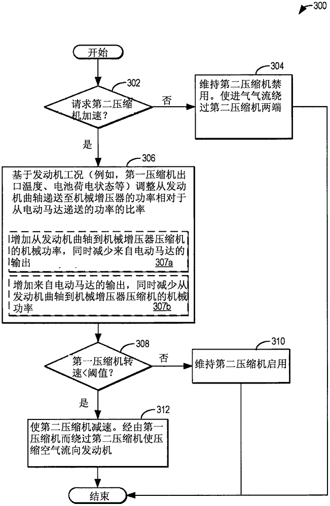
[0013] The following description relates to improvements in engine systems with stepped supercharging devices, such as in figure 1 A system and method for turbocharger speed control in a supercharged engine system. The controller can be configured to execute programs such as Figure 2-Figure 3 example program), thereby increasing the speed of the downstream compressor to reduce the load, and thereby reducing the temperature of the upstream compressor. refer to Figure 4 An example temperature control operation is shown. By operating the second compressor, overheating of the first compressor can be suppressed while continuing to meet driver torque requests.

[0014] figure 1 Aspects of an example engine system 100 including engine 10 are schematically shown. In the depicted embodiment, engine 10 is a supercharged engine including a plurality of staged supercharging devices. Specifically, the engine 10 includes a first supercharging device 13 staged downstream of a second ...


PUM


Abstract

Methods and systems are provided for turbocharger speed control in an engine system having multiple staged charge boosting devices. In one example, compressed air is provided by a turbocharger compressor until a turbocharger speed reaches a limit. Thereafter, a compressor of a downstream supercharger is operated to share the load.

Description

technical field [0001] The present description generally relates to methods and systems for enabling pressure control in a staged charge engine system configured with a turbocharger and a supercharger. Background technique [0002] Engine systems may be configured with a boosting device, such as a turbocharger or supercharger, to provide a charge of charge air and improve peak power output. Using a compressor allows a smaller displacement engine to provide as much power as a larger displacement engine, but with additional fuel economy benefits. Additionally, one or more intake plenums may be staged in series or in parallel with the intake turbocharger to improve the boost response of the turbocharged engine. [0003] An example of a multi-stage intake charge system is shown by Stewart in US Patent 7,958,730. In it, high pressure turbines are staged upstream of low pressure turbines, each turbine being coupled to a corresponding compressor. The multi-stage configuration al...

Claims


Application Information

Patent Timeline
Patent Type & Authority Applications(China)
IPC IPC(8): F02B37/04F02B37/12F02B37/14F02B37/16F02B39/10F02D23/02F02D41/00
CPCF02B37/04F02B37/12F02B37/14F02B37/16F02B39/10F02D23/02F02D41/0007F02D2200/602F02B2037/122F02B2039/168F02D2200/0406F02B37/162Y02T10/12
Inventor 肖柏韬H-R·欧萨乐J·E·M·赫尔斯特伦M·A·桑蒂洛
Owner FORD GLOBAL TECH LLC
Why Eureka
Try Eureka