Shock-absorbing device and unmanned aerial vehicle

A shock absorbing device and aircraft technology, applied in the field of aircraft, to achieve miniaturization, small size, and improved stability

Inactive Publication Date: 2017-01-25
ZHEJIANG HUAFEI INTELLIGENT TECH CO LTD
View PDF10 Cites 7 Cited by
  • Summary
  • Abstract
  • Description
  • Claims
  • Application Information

AI Technical Summary

Problems solved by technology

[0006] The invention provides a shock absorbing device and an unmanned aerial vehicle, the shock absorbing device is used to solve the technical problem of simultaneously isolating high-frequency and low-frequency vibrations under the condition that the shock absorbing device has a small volume

Method used


Image

  • Shock-absorbing device and unmanned aerial vehicle
  • Shock-absorbing device and unmanned aerial vehicle
  • Shock-absorbing device and unmanned aerial vehicle

Examples


Embodiment 1

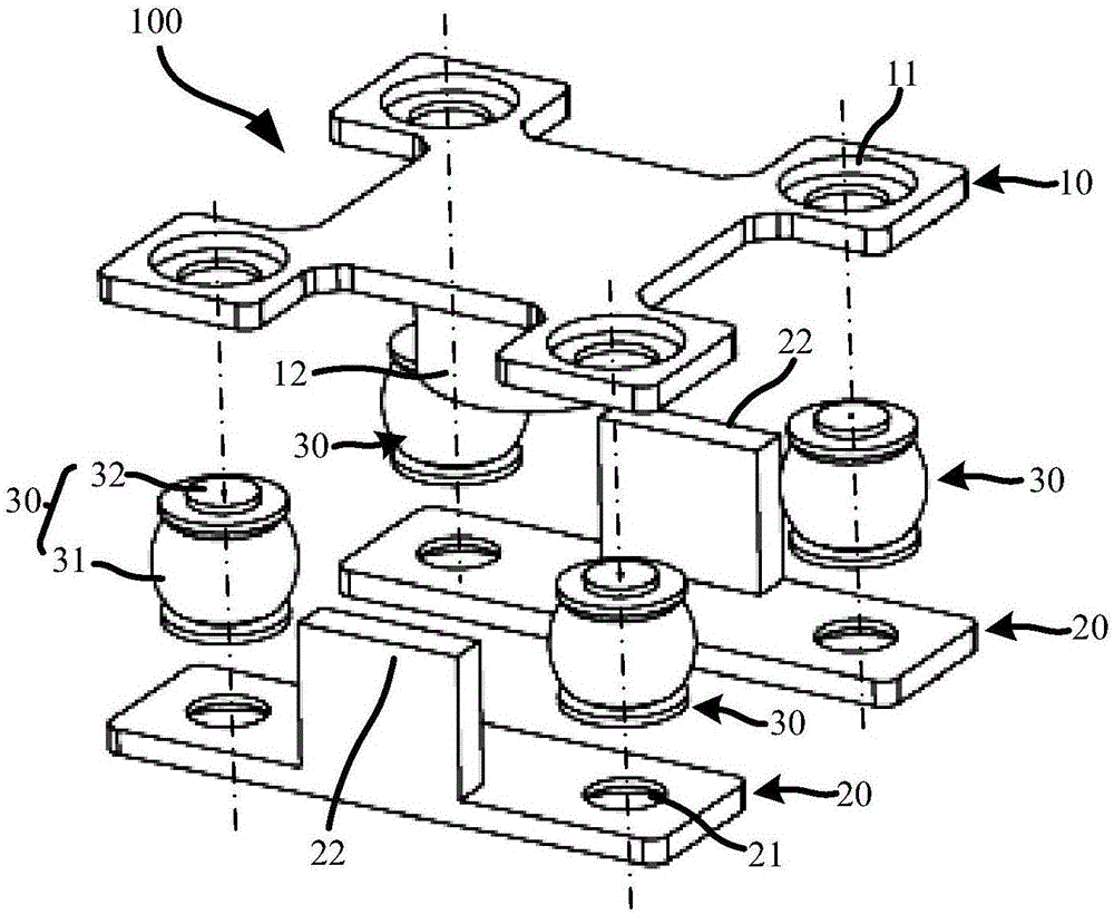
[0051] see figure 2 as shown, figure 2 It is an exploded schematic diagram of a shock absorbing device provided in Embodiment 1. The shock absorbing device 100 provided in this embodiment includes a first connecting piece 10, two second connecting pieces 20 and four shock absorbing pieces 30, each The second connecting piece 20 is connected to the first connecting piece 10 through two shock absorbing pieces 30;

[0052] see image 3 as shown, image 3 It is a schematic cross-sectional structure diagram of a single shock absorber 30 provided in Embodiment 1, each shock absorber 30 includes: a shock absorber body 31, and the shock absorber body 31 includes a flexible cavity 310 with an opening; a throttle valve 32 , the throttle valve 32 is correspondingly arranged at the opening of the flexible cavity 310 ; each throttle valve 32 has at least one throttle hole 321 connecting the interior of the flexible cavity 310 with the external environment.

[0053] In specific implem...

Embodiment 2

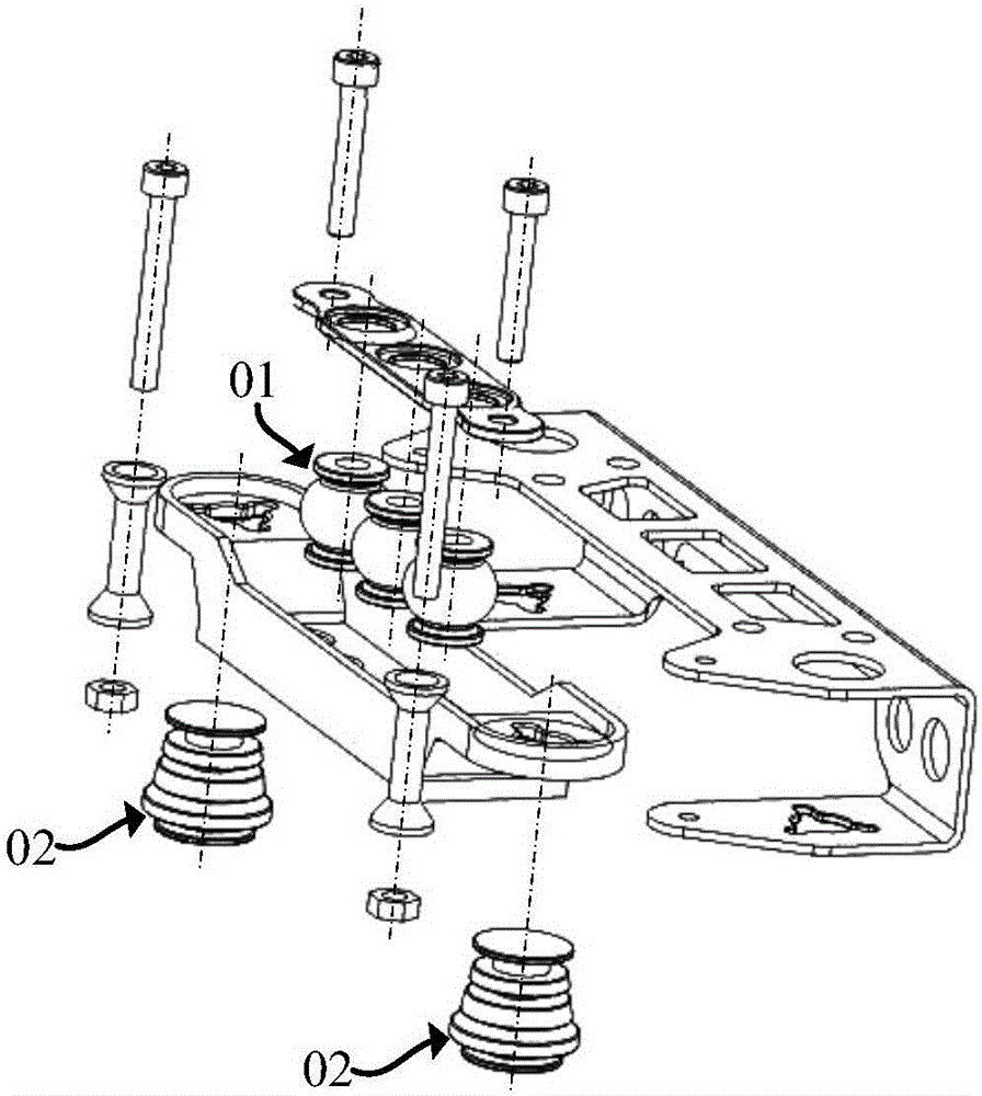
[0084] Based on the same inventive concept, this embodiment provides an unmanned aerial vehicle, see Figure 5 as shown, Figure 5 It is a schematic diagram of the exploded structure of the unmanned aerial vehicle provided in the second embodiment. The unmanned aerial vehicle provided in this embodiment includes the aircraft body 200 and the camera device 300, and also includes a shock absorbing device 100 as provided in the first embodiment above. The camera device 300 passes through A shock absorbing device 100 is mounted on the aircraft body 200 .

[0085] In specific implementation, there is at least one camera, and a plurality of camera devices can be set on an aircraft body according to actual use requirements; The camera device is installed on the aircraft body through a plurality of damping devices, which further improves the shock absorption effect of the camera device.

[0086] In the unmanned aerial vehicle provided in this embodiment, the aircraft body and the im...


PUM


Abstract

The invention relates to the field of aerial vehicles, and in particular relates to a shock-absorbing device and an unmanned aerial vehicle. The shock-absorbing device comprises a first connecting piece, at least one second connecting piece and at least one shock-absorbing part, wherein each second connecting piece is connected with the first connecting piece through the at least one shock-absorbing part; each shock-absorbing part comprises a shock-absorbing part body and at least one throttling valve; each shock-absorbing part body comprises a flexible cavity provided with at least one opening; each throttling valve is correspondingly arranged at one opening of each flexible cavity and is provided with at least one throttling hole for communicating the inner part of each flexible cavity with an external environment. The shock-absorbing parts in the shock-absorbing device can be used for simultaneously isolating low-frequency vibration and high-frequency vibration, so two shock-absorbing parts for respectively isolating the low-frequency vibration and the high-frequency vibration are not needed to be arranged in the shock-absorbing device, and further the use amount of the shock-absorbing parts in the shock-absorbing device is reduced; the high-frequency vibration and the low-frequency vibration are simultaneously isolated under the condition that the shock-absorbing device is enabled to be smaller in size.

Description

technical field [0001] The invention relates to the field of aircraft, in particular to a shock absorbing device and an unmanned aircraft. Background technique [0002] Unmanned aerial vehicles are currently widely used in military or civilian fields, with functions such as surveillance, reconnaissance, and aerial photography. The shooting function of the unmanned aerial vehicle generally needs to be realized by mounting the gimbal. Since the unmanned aerial vehicle will vibrate during the flight, the vibration will affect the stability of the shooting picture or cause the shooting picture to shake after the vibration is transmitted to the gimbal. In order to reduce the gimbal For vibrations received during shooting, a shock absorbing device is generally provided between the gimbal and the fuselage of the unmanned aerial vehicle. [0003] Figure 1a with Figure 1b Shown is a schematic diagram of the exploded structure of two common pan-tilt damping devices, Figure 1a Sho...

Claims


Application Information

Patent Timeline
IPC IPC(8): F16F15/02F16F15/08B64D47/08
CPCF16F15/022B64D47/08F16F15/08
Inventor 陈浩
Owner ZHEJIANG HUAFEI INTELLIGENT TECH CO LTD
Why Eureka
Try Eureka