Gas odorizing control device and gas odorizing system

A control device and gas technology, applied in the pipeline system, gas/liquid distribution and storage, mechanical equipment, etc., can solve the problems of poor odorization effect, odorant liquid difficult to natural gas, etc., to achieve energy saving and precise control of odorization Quantity, real-time correction of the effect of filling concentration

Active Publication Date: 2019-09-03
SICHUAN SHUGU INSTR TECH
View PDF9 Cites 0 Cited by
  • Summary
  • Abstract
  • Description
  • Claims
  • Application Information

AI Technical Summary

Problems solved by technology

Avoid the problem that the traditional odorant liquid is sticky and adsorbed on the pipe wall, which makes it difficult to fully mix the odorant liquid with natural gas, and the odorization effect is poor

Method used


Image

  • Gas odorizing control device and gas odorizing system
  • Gas odorizing control device and gas odorizing system
  • Gas odorizing control device and gas odorizing system

Examples


Embodiment 1

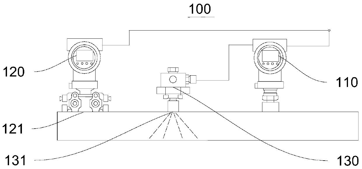
[0032] Please refer to figure 1 This embodiment provides a gas odorization control device 100 , including a control unit 110 , a first detection unit 120 , and an actuator 130 , and the control unit 110 is connected to the first detection unit 120 and the actuator 130 . In this embodiment, the gas pipeline has a first measurement position 121 , and the gas flows from the first measurement position 121 to a preset odorant input position 131 . The first detection unit 120 is located at the first measurement position 121 , and the actuator 130 is located at the odorant input position 131 .

[0033] The first detection unit 120 is used for measuring a first measurement parameter at a first measurement position 121 . There are multiple options for the first measurement parameter, and specific settings can be made according to the transportation requirements in the gas. For example, the first measurement parameter can include the pressure, temperature, flow rate, etc. of the gas in...

Embodiment 2

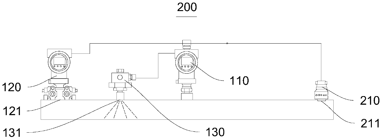
[0038] Please refer to figure 2 , the present embodiment provides a gas odorization control device 200, including a control unit 110, a first detection unit 120, a second detection unit 210, an actuator 130, the control unit 110 and the first detection unit 120, the second detection unit 210 , The actuator 130 is connected.

[0039] The difference from the gas odorizing control device 100 mainly lies in:

[0040] The gas pipeline has a second measurement position 211 , and the flow of gas is as follows: the gas flows from the first measurement position 121 to the second measurement position 211 through the preset odorant input position 131 . The second detection unit 210 is located at the second measurement position 211 . The second detection unit 210 is used for measuring the second measurement parameter at the second measurement position 211 . There are multiple options for the second measurement parameter, and specific settings can be made according to the transportatio...

Embodiment 3

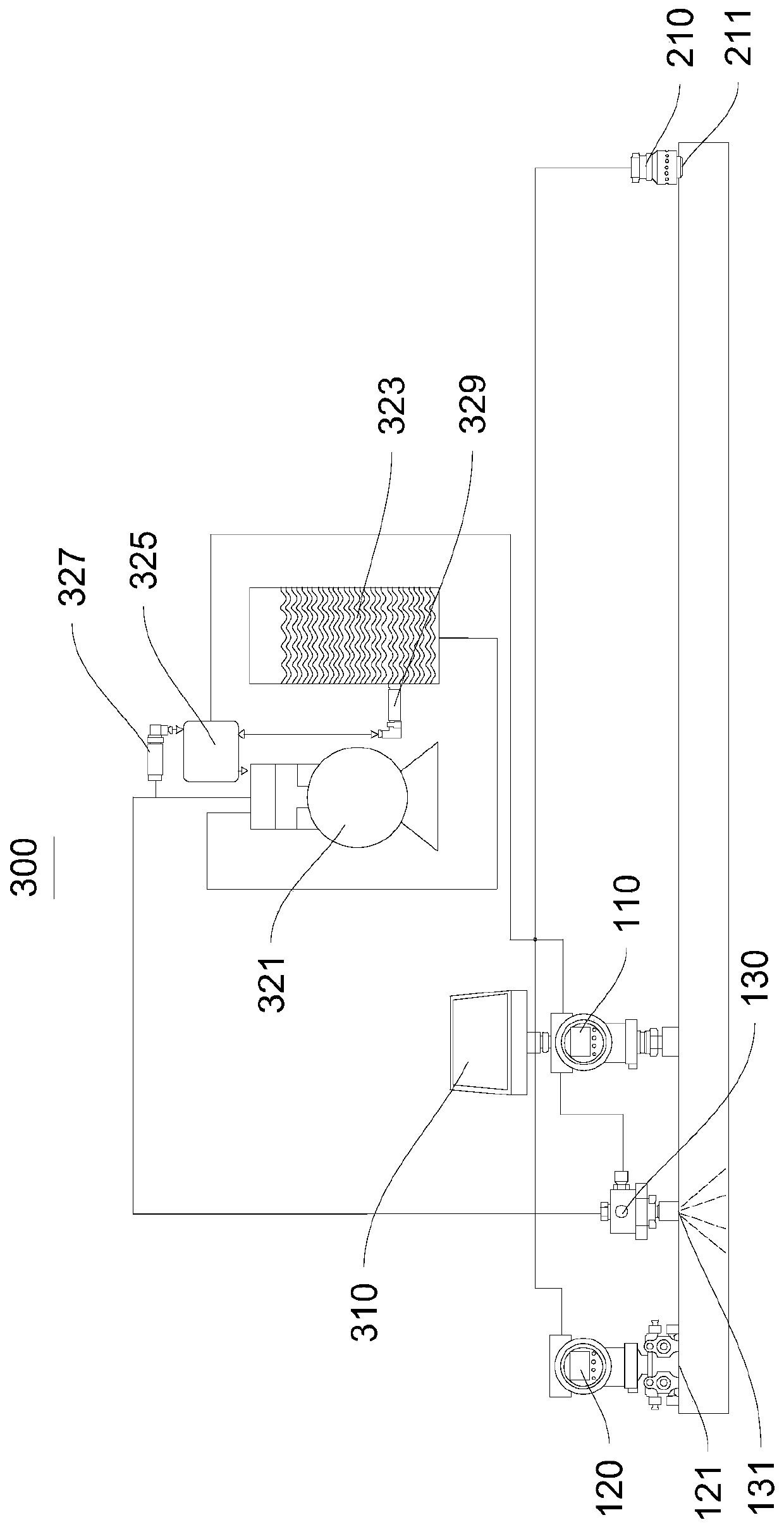
[0044] Please refer to image 3 This embodiment provides a gas odorizing system 300, including a power unit 310, a conveying device 320, and a gas odorizing control device 200, and the power unit 310 and the conveying device 320 are respectively connected to the gas odorizing control device 200.

[0045] In this embodiment, the power device 310 is a solar panel assembly, which provides power to the gas odorization control device 200. In other embodiments of the present invention, the power device 310 can also be other power supply equipment, such as a generator.

[0046] The conveying device 320 includes a pump 321, an odorant storage tank 323, a pressure stabilizer 325, and a pressure gauge 327. The pump 321 is connected to the odorant storage tank 323, and the pressure stabilizer 325 is connected to the pump 321 and the odorant storage tank 323 respectively. .

[0047] The pressure gauge 327 measures the pressure value output from the pump 321 and feeds the pressure value b...


PUM


Abstract

The invention relates to the technical field of fuel gas odorizing and provides a fuel gas odorizing control device. The fuel gas odorizing control device comprises a control unit, a first detection unit and an execution mechanism, wherein the execution mechanism and the first detection unit are both in data communicating connection with the control unit, and the flowing direction of fuel gas in a pipeline is from a first measurement position to an odorizing agent inputting device. The first detection unit is arranged at the first measurement position and is used for measuring a first measurement parameter of the fuel gas at the first measurement position. The control unit receives the first measurement parameter and controls the execution mechanism to input an odorizing agent according to the first measurement parameter. Therefore, the odorizing amount can be accurately controlled, the filling concentration can be corrected in real time, and pipeline fuel gas can be quickly, conveniently and effectively odorized. The invention further provides a fuel gas odorizing system. The fuel gas odorizing system comprises a power device, a delivery device and the fuel gas odorizing control device. The power device and the delivery device are respectively connected with the fuel gas odorizing control device, timely and accurate filling is achieved, and raw materials and energy sources are saved.

Description

technical field [0001] The invention relates to the technical field of gas odorization, in particular to a gas odorization control device and a gas odorization system. Background technique [0002] Both industrial production and residential buildings have a lot of gas supply systems, and some gas supply systems require that no gas leakage or leakage can be detected in time. Take natural gas as an example. Today, natural gas is widely used in gas supply systems. However, due to the physical characteristics of natural gas, which is colorless, odorless or slightly odorous, once a leak is difficult to detect in time, there is a great potential safety hazard. In order to detect gas leakage in time and take effective measures to control the leakage, it is usually necessary to install an alarm during the supply process of town gas so as to warn the gas leakage situation according to the odor concentration in the air. Usually the minimum amount of odorant in the gas should comply w...

Claims


Application Information

Patent Timeline
Patent Type & Authority Patents(China)
IPC IPC(8): F17D1/02F17D3/12F17D3/01
Inventor 银红春王我
Owner SICHUAN SHUGU INSTR TECH
Why Eureka
Try Eureka