Split absorbing-type heat exchange unit and heat exchange method thereof
A heat exchange unit, absorption heat pump technology, applied in adsorption machines, refrigerators, energy-saving heating/cooling, etc., can solve the problem of large volume, increase the primary side hot water supply, return water temperature difference, transportation , installation difficulties and other problems, to achieve the effect of smooth flow of solution, convenient transportation and installation work, and reduced transportation size
- Summary
- Abstract
- Description
- Claims
- Application Information
AI Technical Summary
Problems solved by technology
Method used
Image
Examples
Embodiment 1
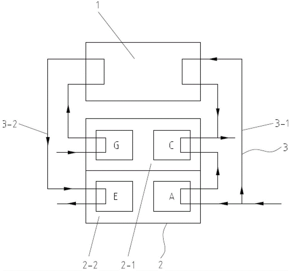
[0028] Such as figure 1 As shown, a split type absorption heat exchange unit, the heat exchange unit includes a hot water absorption heat pump 2, a water-water heat exchanger 1 and a water system 3;
[0029] The hot water type absorption heat pump includes two split bodies 2-1, 2-2, one split body includes a generator G and a condenser C, and the other split body includes an absorber A and an evaporator E;
[0030] The waterway system 3 includes two parts: the primary side waterway system 3-2 and the secondary side waterway system 3-1: the primary side waterway system 3-2 adopts a series connection mode, and is sequentially connected to the generator G, water-water exchange The high-temperature side of the heater 1 and the evaporator E return to the centralized heat source; the secondary side water system 3-1 adopts a parallel connection mode and is divided into two circuits, one of which is connected to the low-temperature side of the water-water heat exchanger 1, and the oth...
Embodiment 2
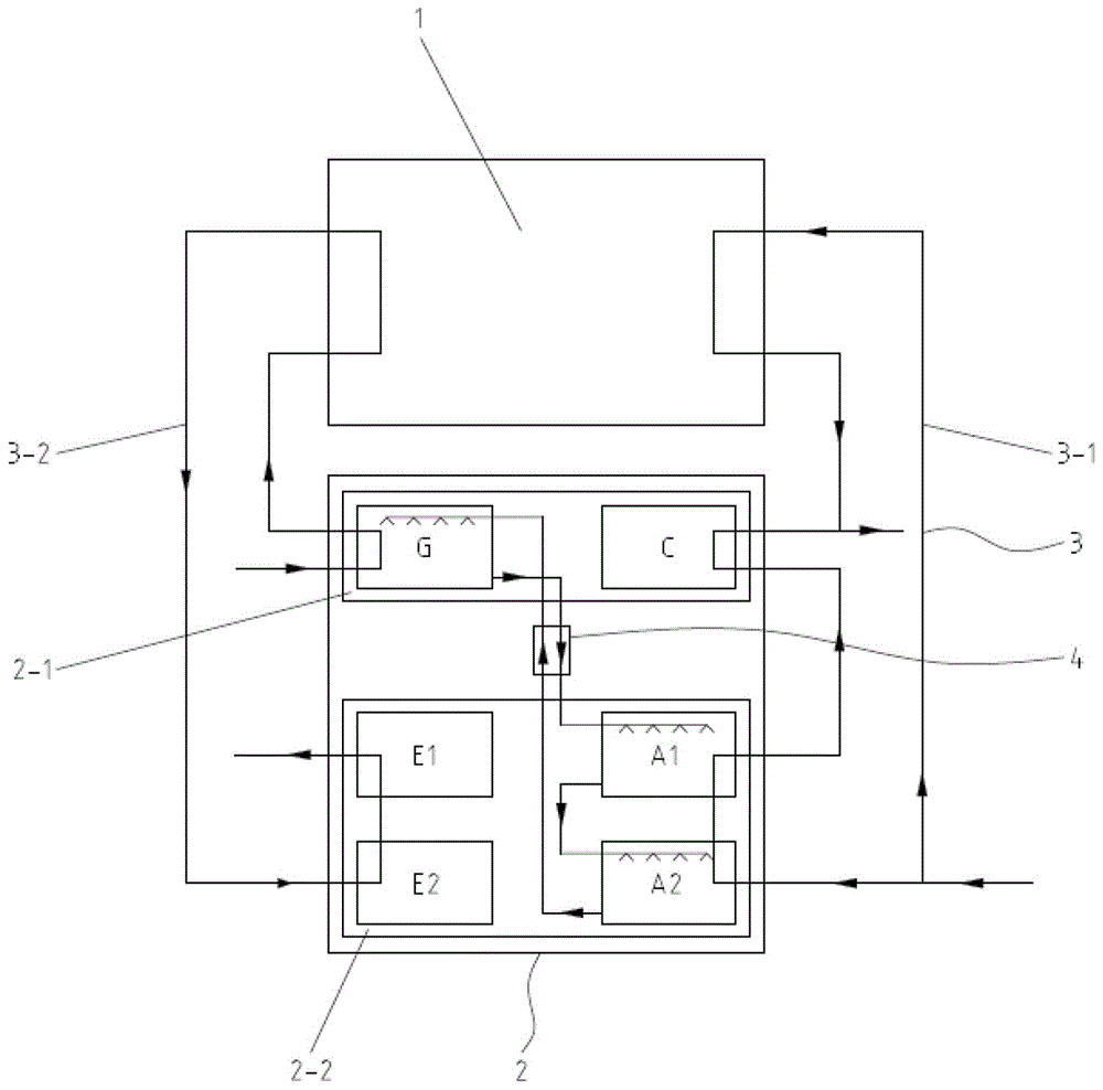
[0035] This embodiment is an improvement made on the basis of Embodiment 1. For the same part as Embodiment 1 in this embodiment, please refer to the content disclosed in Embodiment 1 for understanding, and the content disclosed in Embodiment 1 should also be used as this embodiment. The content of the example will not be repeated here.
[0036] Such as figure 2 As shown, the absorber A includes a high-pressure absorber A2 and a low-pressure absorber A1; the evaporator E includes a high-pressure evaporator E2 and a low-pressure evaporator E1; - The high temperature side of the water heat exchanger 1, the high pressure evaporator E2, and the low pressure evaporator E1 return to the centralized heat source; the secondary side waterway system 3-1 is connected to the low temperature side of the water-water heat exchanger 1 in one way, and the other way Connect high-pressure absorber A2, low-pressure absorber A1, and condenser C in sequence, and the two paths of secondary water a...
Embodiment 3
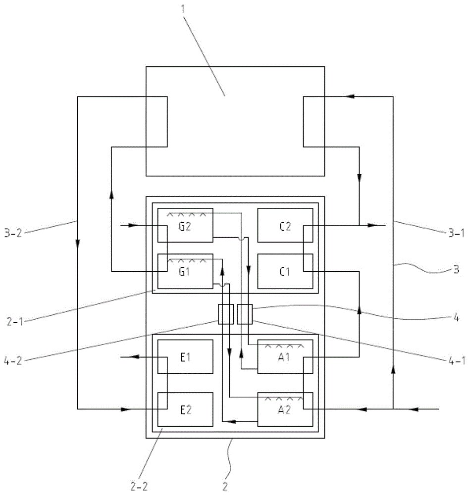
[0042] This embodiment is an improvement made on the basis of Embodiment 1. For the same part as Embodiment 1 in this embodiment, please refer to the content disclosed in Embodiment 1 for understanding, and the content disclosed in Embodiment 1 should also be used as this embodiment. The content of the example will not be repeated here.
[0043] Such as image 3 As shown, the absorber A includes a high-pressure absorber A2 and a low-pressure absorber A1; the evaporator E includes a high-pressure evaporator E2 and a low-pressure evaporator E1; the generator G includes a high-pressure generator G2 and a low-pressure generator G1 The condenser C includes a high-pressure condenser C2 and a low-pressure condenser C1, and the primary side water system 3-2 is connected to the high-pressure generator G2, the low-pressure generator G1, the high-temperature side of the water-water heat exchanger 1, the high-pressure The evaporator E2 and the low-pressure evaporator E1 return to the cen...
PUM
 Abstract
Description
Claims
Application Information
 - R&D
- Intellectual Property
- Life Sciences
- Materials
- Tech Scout
- Unparalleled Data Quality
- Higher Quality Content
- 60% Fewer Hallucinations
Browse by: Latest US Patents, China's latest patents, Technical Efficacy Thesaurus, Application Domain, Technology Topic, Popular Technical Reports.
© 2025 PatSnap. All rights reserved.Legal|Privacy policy|Modern Slavery Act Transparency Statement|Sitemap|About US| Contact US: help@patsnap.com


