Movable steam-injection boiler and moving method thereof

A steam injection boiler and mobile technology, applied in steam boilers, steam generation, earthwork drilling and production, etc., can solve the problems of large steam injection needs in heavy oil blocks, long steam injection time for single wells, and affecting oil production speed, etc., to achieve The effect of reducing the transportation size, occupying a small area, and increasing the output of heavy oil

Pending Publication Date: 2022-04-12
PETROCHINA CO LTD
View PDF0 Cites 0 Cited by
  • Summary
  • Abstract
  • Description
  • Claims
  • Application Information

AI Technical Summary

Problems solved by technology

[0003] Traditional steam injection boilers, especially large steam injection boilers with a rated evaporation capacity of 23t / h, are all skid-mounted and fixed structures. They are fixedly installed in the factory building for steam injection through the steam injection pipe network, and cannot be moved casually.
However, with the development of heavy oil old blocks, the amount of steam injection decreased, making some 23t / h steam injection boilers idle and out of service
However, according to the reservoir development plan, the newly developed heavy oil block requires a large amount of steam injection. The 11.2t / h and 9.2t / h movable furnaces originally assumed the task of steam injection. The boiler evaporation is low and the steam injection rate is slow. long, greatly affecting the oil recovery rate of this block
If a 23t / h steam injection boiler is rebuilt in a new block, the construction cost is relatively high; if the steam injection boiler in the old block is relocated to a new block, the factory building needs to be demolished, and the steam injection boiler is lifted and relocated by a large crane. It will cost about 8.13 million yuan to relocate a steam injection boiler and build a new steam injection station, which is a relatively large investment

Method used


Image

  • Movable steam-injection boiler and moving method thereof
  • Movable steam-injection boiler and moving method thereof
  • Movable steam-injection boiler and moving method thereof

Examples


Embodiment Construction

[0047] In order to have a clearer understanding of the technical features, purposes and effects of the present invention, the specific implementation manners of the present invention will now be described with reference to the accompanying drawings.

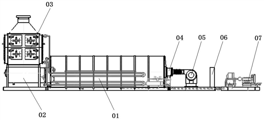
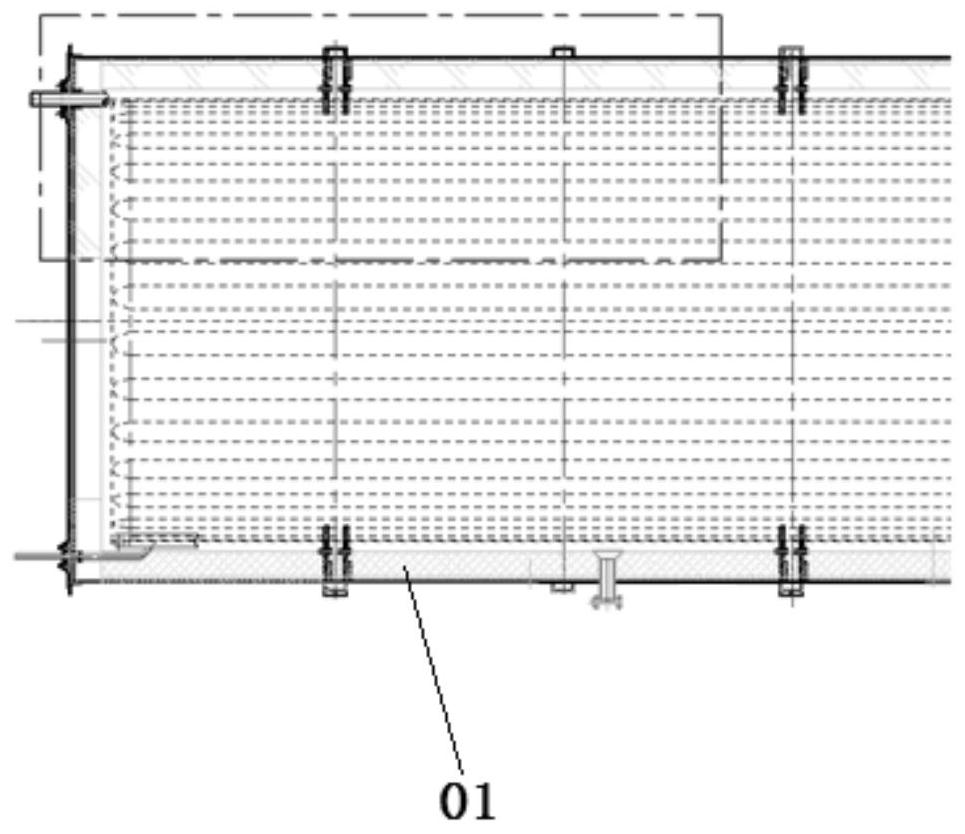
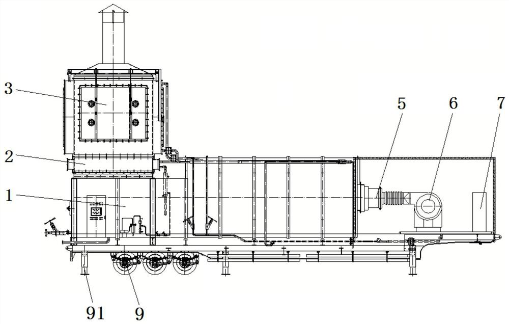
[0048] Such as Figure 3 to Figure 11As shown, this embodiment provides a mobile steam injection boiler, including a first module, a second module, a third module, a fourth module and a fifth module.

[0049] Among them, the first module includes boiler operation panel 7, burner 5, blower 6, radiation section 1 and water-water heat exchanger 4, the second module includes convection section 3, and the third module includes plunger pump 8 and air compressor , the fourth module includes the power distribution system, and the fifth module includes the venting equipment. The first module is installed on the first transport vehicle 9, the convection section 3 is installed above the tail of the radiation section 1, and the first module...


PUM


Abstract

The invention relates to a mobile steam-injection boiler and a moving method thereof, the mobile steam-injection boiler comprises a first module, a second module, a third module, a fourth module and a fifth module, the first module comprises a boiler operation board, a combustor, an air blower, a radiation section and a water-water heat exchanger, and the second module comprises a convection section. The third module comprises a plunger pump and an air compressor, the fourth module comprises a power distribution system, and the fifth module comprises emptying equipment. The first module is installed on a first transport vehicle, the convection section is installed above the tail of the radiation section, and the first module, the second module, the third module, the fourth module and the fifth module are connected through corresponding pipelines. The steam injection boiler can be recycled, the steam injection requirement of a newly developed thickened oil block is met, the problem of the steam injection requirement of the newly developed thickened oil block is solved, and investment is reduced.

Description

technical field [0001] The invention relates to the technical field of heavy oil development, in particular to a mobile steam injection boiler and a moving method thereof. Background technique [0002] The technical parameters of the existing steam injection boiler are: rated evaporation: 23t / h; rated steam pressure: 17.2MPa; rated steam temperature: 353°C; steam dryness: 80%; size: 27750×4110×8470mm (including chimney); Fuel: oil, gas; control mode: PLC+touch screen. The structure of the steam injection boiler is as follows figure 1 and figure 2 As shown, it includes a boiler body, a water-water heat exchanger, a burner 04, a blower 05, a boiler operation panel 06 (that is, an automatic instrument) and a plunger pump 07. The boiler body includes radiation section 01, transition section 02 and convection section 03. The radiation section 01 has a cylindrical structure, and the heating surface adopts a serpentine reciprocating structure. Radiation heat transfer is mainly ...

Claims


Application Information

Patent Timeline
Patent Type & Authority Applications(China)
IPC IPC(8): F22B31/08F22B33/12E21B43/24
Inventor 于显永陈庆凯林军崔连才万腾飞卞家忠单祥斌程滨刘祎阳郭鲁冰荆树鹏金龙朱国丰李春辉伍兴旺
Owner PETROCHINA CO LTD
Why Eureka
Try Eureka