Computing method for aero-engine barycenter
A technology of aero-engine and calculation method, applied in the field of aero-engine to achieve the effect of strong universality
- Summary
- Abstract
- Description
- Claims
- Application Information
AI Technical Summary
Problems solved by technology
Method used
Image

Examples
Embodiment Construction
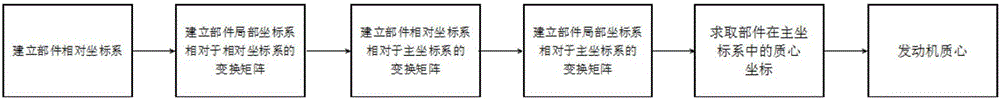
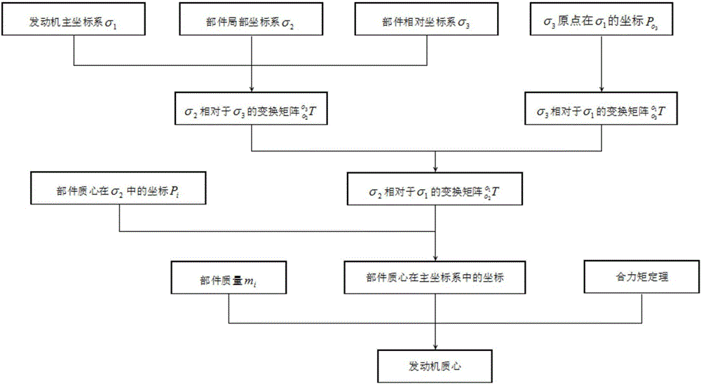
[0026] combined with Figure 1-3 Describe this embodiment, the theoretical basis of the method for calculating the center of mass of an aeroengine in this embodiment is the homogeneous coordinate transformation method and the resultant moment theorem, and calculate according to the following steps:
[0027] a. Establish the component local coordinate system σ 2 Relative to the relative coordinate system σ 3 The transformation matrix of
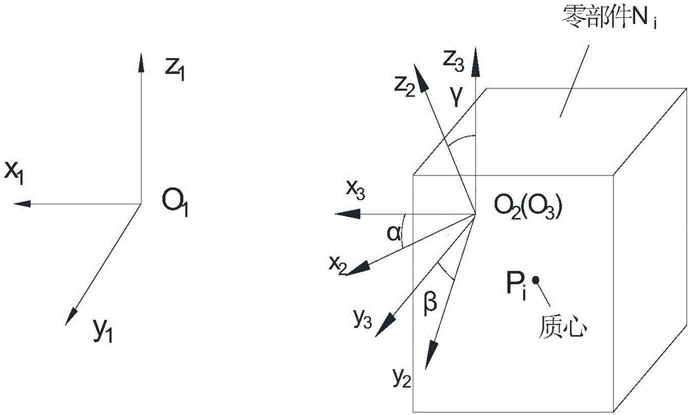
[0028] a11. At the position of the main engine installation node, establish the engine main coordinate system σ 1 =[O 1 ; x 1 ,y 1 ,z 1 ];
[0029] a12. Determine the component local coordinate system σ according to the component mass characteristic file 2 =[O 2 ; x 2 ,y 2 ,z 2 ];
[0030] a13. Through the local coordinate system σ 2 Origin O 2 Established with the principal coordinate system σ 1 The relative coordinate system σ of each axis in the same direction 3 =[O 3 ; x 3 ,y 3 ,z 3 ], the coordinate system σ 2 with...
PUM
 Abstract
Description
Claims
Application Information
 - Generate Ideas
- Intellectual Property
- Life Sciences
- Materials
- Tech Scout
- Unparalleled Data Quality
- Higher Quality Content
- 60% Fewer Hallucinations
Browse by: Latest US Patents, China's latest patents, Technical Efficacy Thesaurus, Application Domain, Technology Topic, Popular Technical Reports.
© 2025 PatSnap. All rights reserved.Legal|Privacy policy|Modern Slavery Act Transparency Statement|Sitemap|About US| Contact US: help@patsnap.com