Structure and preparation method of a phosphogypsum slag discharge yard

A technology for phosphogypsum and slag discharge yards, which is applied in the direction of manufacturing tools, ceramic molding machines, ceramic molding workshops, etc., and can solve the problems of shortening the belt frame, belt service life, high risk factor for slag discharge operators, and adaptability of the belt machine frame In order to achieve the effect of reducing input cost, reducing slope height and reducing risk factor

Active Publication Date: 2019-01-15
GUIZHOU KAILIN GRP CO LTD
View PDF6 Cites 0 Cited by
  • Summary
  • Abstract
  • Description
  • Claims
  • Application Information

AI Technical Summary

Problems solved by technology

[0002] In the wet-process phosphoric acid production process, a large amount of phosphogypsum waste residue will be produced, but due to the long-term discharge of phosphogypsum waste residue in the phosphogypsum slag discharge site, the piled material will cause a high slope of the slag discharge site, and now The belt conveyor setting methods in the prior art are all set from top to bottom or horizontally, so that it can achieve the purpose of reducing energy consumption, and in the above-mentioned setting process, the belt conveyor frame is set so that the belt conveyor frame can Adapt to the height of the slag discharge field, and then achieve the purpose of slag discharge and reduce energy consumption; however, the above-mentioned settings easily cause the belt frame to be unstable, making the belt frame easily deformed, and shortening the service life of the belt frame and belt ; And it also makes the risk factor of slag discharge workers higher
[0003] For this reason, many steel products and steel bars are used in the prior art to improve the safety factor. By erecting stairs, platforms, guardrails, etc., the safety factor of the operating staff is improved and the production safety risk is reduced; however, the stairs erected by steel bars , platform, and guardrail With the use of the belt conveyor frame year by year, it will also cause damage to the belt conveyor frame when it is deformed, which will affect the further operation; and use steel bars and other materials to carry out stairs, guardrails, and platforms. setting, it is still difficult to increase the stability of the belt conveyor, and it will also lead to higher production costs
[0004] Moreover, the slope height of the phosphogypsum slag discharge yard generally has a drop of more than 100 meters, and it is difficult to make flexible changes according to the geographical location and production requirements of the site, which leads to a safe setting of the belt conveyor frame when entering the slag yard. In the process, it needs to be re-produced and processed, resulting in poor adaptability of the belt conveyor frame

Method used


Image

  • Structure and preparation method of a phosphogypsum slag discharge yard
  • Structure and preparation method of a phosphogypsum slag discharge yard
  • Structure and preparation method of a phosphogypsum slag discharge yard

Examples


Embodiment 1

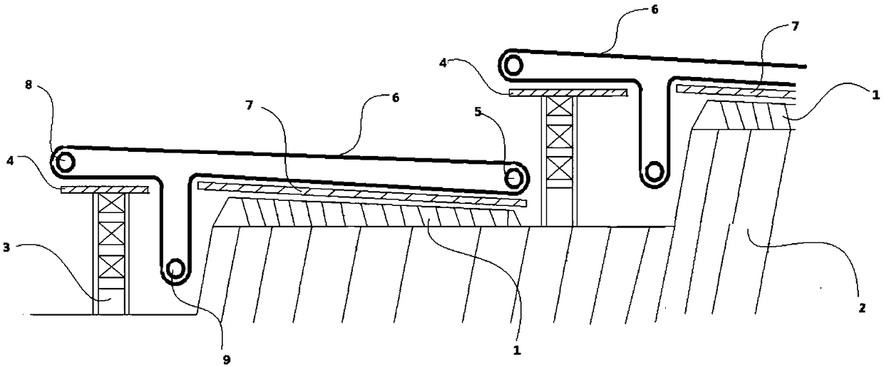
[0037] Such as figure 1 As shown, a structure of a phosphogypsum slag discharge yard is provided with a base layer 2, and the base layer 2 is stepped. On the same step of the base layer 2, a rolling layer 1 and a high tower 3 are arranged, and the rolling layer 1 is located on the high Before the tower 3, the upper surface of the rolling layer 1 is laid with a prefabricated slab 7; there is a gap between the rolling layer 1 and the high tower 3 on the next step, and forms a pit together with the base layer 2; the top of the high tower 3 is provided with a Platform 4; the prefabricated plate 7 is provided with a first motor 5 near the end of the high tower 3 on the same ladder, a third motor 9 is provided in the above-mentioned pit, and a first motor 9 is provided on the platform 4 directly opposite to the first motor 5. Two motors 8, the first motor 5, the second motor 8, and the third motor 9 are connected by a conveyor belt 6. During the slag discharge process, the conveyor...

Embodiment 2

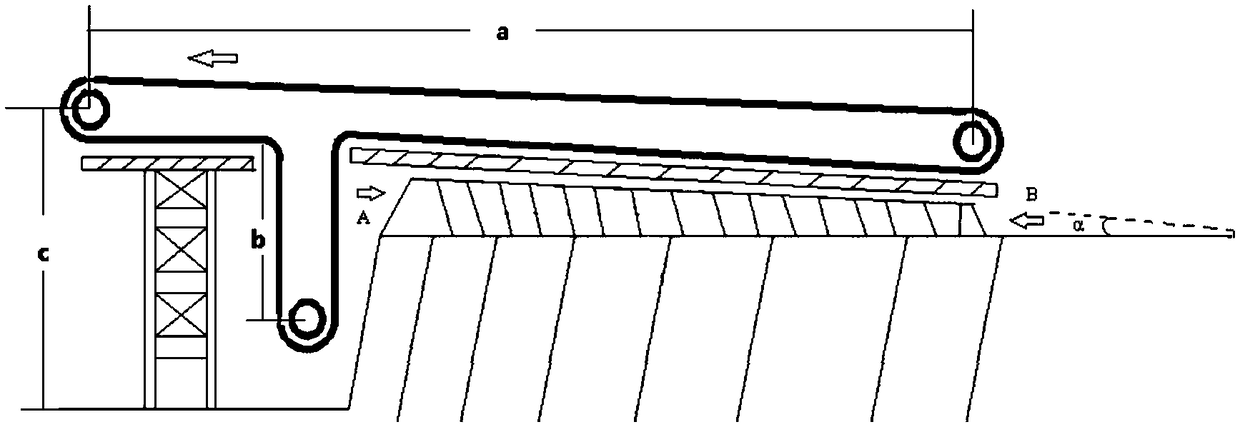
[0039] Such as figure 2 Shown, on the basis of embodiment 1, others are all the same as embodiment 1, a kind of structure of phosphogypsum slag discharge yard, described rolling layer 1 is inclined to the high tower 3 ends on the same ladder, and with The horizontal plane of the base layer 2 forms an included angle α. The size of the included angle is determined by the structure of the rolling layer, especially by the length of the rolling layer, and the height g of the rolling layer near the end of the high tower and the height e away from the end of the high tower 3 are stable and determined , when the length of the laminated layer is longer, the included angle will be smaller.

[0040] In addition, in the process of determining the included angle, it can also be determined by the thickness of the rolling layer after determining the length of the rolling layer.

Embodiment 3

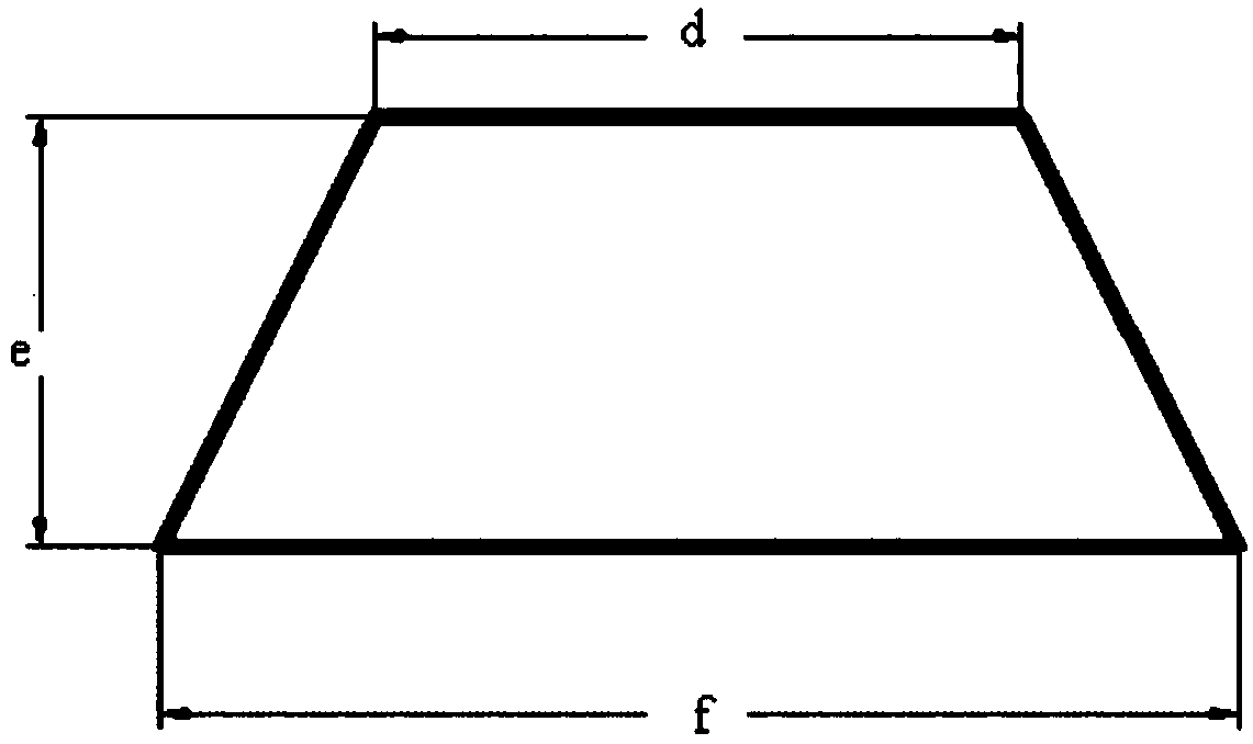
[0042] Such as figure 2 , 3 , 4, on the basis of embodiment 1, others are all the same as embodiment 1, a structure of a phosphogypsum slag discharge yard, the end face of the high tower 3 ends of the described rolling layer 1 close to the same ladder is trapezoidal , the length f of the lower bottom is 8m, the length d of the upper bottom is 6m, and the height g is 1.5m; 6m, height e is 4m. The pit is 10m deep; the third motor 9 is arranged on the bottom of the pit. The distance b from the center of the third motor 9 to the horizontal plane of the platform 4 is 8m. The step horizontal distance c from the center of the second motor 8 to the base layer 2 is 12m. The distance a between the center of the first motor 5 and the center of the second motor 8 is 80m. The length of the rolling layer 1 is 60-70m.


PUM

PropertyMeasurementUnit
lengthaaaaaaaaaa
lengthaaaaaaaaaa
lengthaaaaaaaaaa

Abstract

The invention relates to the technical field of ardealite slag discharging field structures, in particular to a structure of an ardealite slag discharging field and a preparation method of the structure. By obliquely arranging a compacted layer, in the process of ardealite slag discharging treatment of the slag discharging field, a belt conveyor can effectively convey materials upwards, and a third motor is arranged in a pit in a combined mode, so that the power consumption of conveying with the belt conveyor is reduced; the stability of the belt conveyor in the conveying process is improved, deformation of a rack of the belt conveyor can be reduced, and the safety coefficient is increased; and by arranging the compacted layer, the rack of the belt conveyor can effectively adapt to various slag discharging fields, and the input cost of the rack of the belt conveyor is reduced.

Description

technical field [0001] The invention relates to the technical field of phosphogypsum slag discharge yard structure, in particular to a structure of phosphogypsum slag discharge yard and a preparation method thereof. Background technique [0002] In the wet-process phosphoric acid production process, a large amount of phosphogypsum waste residue will be produced, but due to the long-term discharge of phosphogypsum waste residue in the phosphogypsum slag discharge site, the piled material will cause a high slope of the slag discharge site, and now The belt conveyor setting methods in the prior art are all set from top to bottom or horizontally, so that it can achieve the purpose of reducing energy consumption, and in the above-mentioned setting process, the belt conveyor frame is set so that the belt conveyor frame can Adapt to the height of the slag discharge field, and then achieve the purpose of slag discharge and reduce energy consumption; however, the above-mentioned sett...

Claims


Application Information

Patent Timeline
Patent Type & Authority Patents(China)
IPC IPC(8): B28B15/00C04B28/14
CPCB28B15/00C04B28/143C04B7/00C04B14/02C04B18/24
Inventor 秦勇甘贵
Owner GUIZHOU KAILIN GRP CO LTD
Why Eureka
Try Eureka