Rotary kiln fluidized roasting device and roasting process

A fluidized roasting and roasting process technology, applied in the field of metallurgy, can solve the problems of poor mineral reduction effect, low heat utilization rate, energy waste, etc., and achieve the effects of improving smelting effect, improving heat utilization rate, and reducing energy consumption

A fluidized roasting and roasting process technology, applied in the field of metallurgy, can solve the problems of poor mineral reduction effect, low heat utilization rate, energy waste, etc., and achieve the effects of improving smelting effect, improving heat utilization rate, and reducing energy consumption

CN106369994BInactive Publication Date: 2019-02-15王彬海 +2

Image

  • Rotary kiln fluidized roasting device and roasting process
  • Rotary kiln fluidized roasting device and roasting process
  • Rotary kiln fluidized roasting device and roasting process

Examples


Embodiment 1

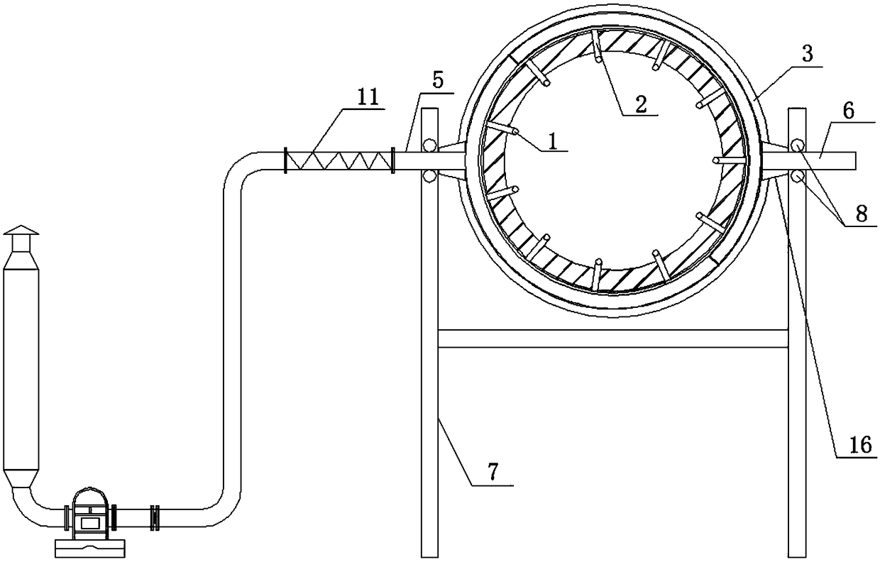
[0047] Rotary kiln fluidized roasting device has the advantages of high heat utilization rate, high volatile matter volatilization efficiency, good refining effect, low energy consumption and low smelting cost, such as figure 1 , figure 2 , image 3 , Figure 4 As shown, the following structure is specially set up: it includes a rotary kiln body, a total wind jacket and a blower connected in sequence, the total wind jacket is sleeved on the outer wall of the rotary kiln body, and the blower is arranged on the general wind jacket of the exterior. Wherein, the rotary kiln body is provided with a plurality of through holes with a diameter of 70mm along the circumferential direction in the middle of the middle temperature section, and the main air sleeve communicates with the interior of the rotary kiln body through the through holes.

[0048] Wherein, the total air jacket includes two air jacket retaining rings 3 and an air heating jacket clamped between the air jacket retain...

Embodiment 2

[0053] This embodiment is further optimized on the basis of the above-mentioned embodiments, further to better realize the present invention, such as figure 2 As shown, the following arrangement structure is adopted in particular: a hose 11 communicates between the air blower and the air heating sleeve inlet pipe 5 . Because the rotary kiln will move to the kiln head due to its own gravity during operation, and will drive the air heating sleeve 4 to move at the same time, which makes the air heating sleeve inlet pipe 5 welded on the air heating sleeve 4 and the blower The position between them is constantly changing, and the hose 11 can offset the relative displacement between the air blower and the air heating sleeve inlet pipe 5, and can improve the connection reliability between the air blower and the air heating sleeve 4.

Embodiment 3

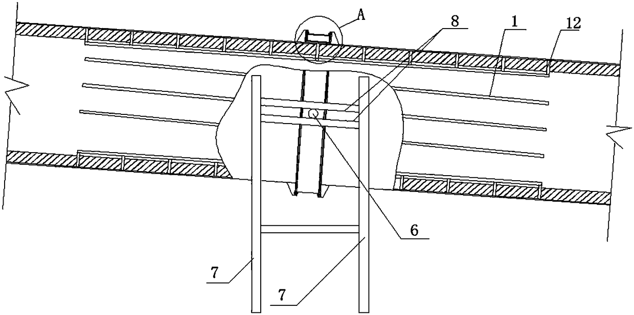
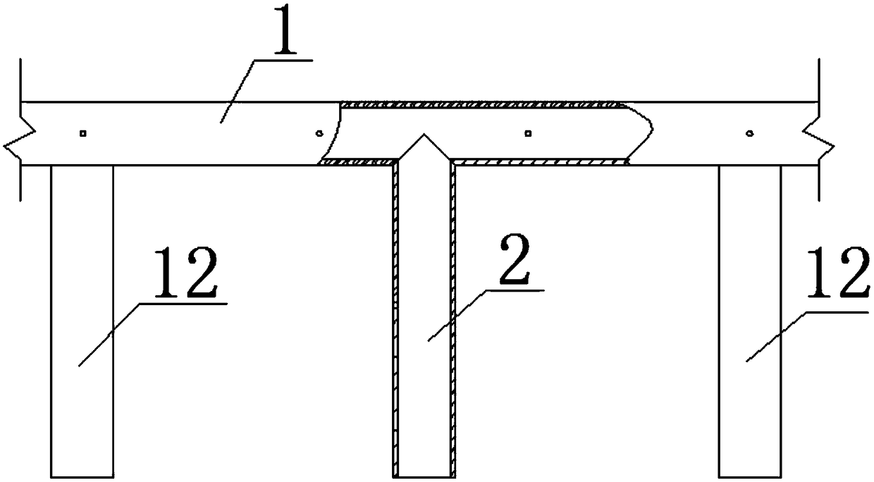
[0055] This embodiment is further optimized on the basis of any of the above embodiments, further to better realize the present invention, such as figure 1 , figure 2 , image 3 , Figure 4 As shown, the following arrangement structure is adopted in particular: an air injection device is arranged inside the rotary kiln body, and the air injection device includes a plurality of air injection main pipes 1 laid obliquely along the inner wall of the rotary kiln, and the middle part of the air injection main pipe 1 The air inlet pipe 2 is fixed to the inner wall of the rotary kiln body, and the air inlet pipe 2 and the air heating sleeve 4 communicate with the gap formed between the rotary kiln body; A plurality of jet holes with a diameter of 5mm are provided, and the specific number of jet holes is selected according to actual usage conditions. The gas is sprayed into the interior of the rotary kiln body through the gas injection holes, and the pressure of the gas injected in...


PUM


Abstract

The invention discloses a rotary kiln fluidization roasting device and process. The rotary kiln fluidization roasting device comprises a rotary kiln body, a total air sleeve and an air blower which are sequentially communicated, the total air sleeve is connected to the outer wall of an intermediate temperate section of the rotary kiln body in a sleeving manner, and the air blower is arranged on the exterior of the total air sleeve. An air spraying device is communicated between the rotary kiln body and the total air sleeve and is arranged inside the rotary kiln body. A using method of the rotary kiln fluidization roasting device includes the following steps of burdening, feeding, rotary kiln starting, roasting or burning, smoke collecting, kiln slag collecting, smoke treatment and kiln slag treatment. Compared with the prior art, the air blower blows air to the interior of the rotary kiln body, and therefore the oxygen content of air in the rotary kiln body is increased; meanwhile, materials are stirred, so that the contact areas between the materials and the air are increased, and the ingredients of pulverized coal are reduced; and the rotary kiln fluidization roasting device and process have the beneficial effects of being high in using rate, high in volatilization efficiency of volatile matter, good in refining effect, low in energy consumption and low in smelting cost.

Description

technical field [0001] The invention relates to the technical field of metallurgy, in particular to a rotary kiln fluidized roasting device and a roasting process. Background technique [0002] The rotary kiln is a rotary kiln, which is a cylindrical body with a length of 32-50m and a diameter of 1800-3500mm. It has a kiln tail, a kiln body and a kiln head connected in sequence. It is the feeding part of the rotary kiln. Fuels such as coal powder and natural gas are sent into the rotary kiln from the kiln head, and minerals mixed with coal powder and other reducing agents are added to the rotary kiln through the kiln tail. It is a low-temperature section, a medium-temperature section and a high-temperature section. The rotary kiln is installed horizontally on 3-5 sets of supporting wheels for support, and the rotary motion is realized through the transmission of the gear and ring gear, and the inclination angle between the rotary kiln and the ground is 3-5%. The kiln tail i...

Claims


Application Information

Patent Timeline
15 Feb 2019
Publication
CN106369994B
IPC
F27B7/12; F27B7/34; F27B7/36
CPC
F27B7/12; F27B7/34; F27B7/362; F27B2007/367; F27M2003/03
Inventors
王彬海; 梁瑞兵