
Method and device for improving concentration speed of diameter-variable concentration cup

A technology of speed and sub-device, which is applied in the field of increasing the concentration rate of variable-diameter concentration cups, can solve the problems of speeding up the concentration rate, increasing gas consumption, and increasing the cost of the experiment, so as to reduce the exposed area, save the concentration time, and save the cost of the experiment. Effect

Active Publication Date: 2017-02-01
BEIJING POLYTECH INSTR
View PDF8 Cites 0 Cited by
  • Summary
  • Abstract
  • Description
  • Claims
  • Application Information

AI Technical Summary

Problems solved by technology

[0002] When the nitrogen blowing concentrator is used for the concentration of a small volume of solvent, the gas outlet direction of the blowing needle is perpendicular to the liquid surface. The disadvantage of this concentration method is that as the liquid level drops, it is necessary to continuously lower the blowing needle or continuously increase the gas pressure to achieve The purpose of destroying the saturated vapor pressure of the liquid surface, but the adjustment of the height of the blowing needle needs to be manually guarded, which consumes the time and energy of the experimenter
[0003] When the existing nitrogen blowing concentrator is used for large-volume concentration, in order to increase the concentration rate, the air outlet of the blowing needle is generally blown out at a 45° angle along the tangential direction of the cup wall, so that the liquid surface rotates continuously, thereby speeding up the concentration rate. Volumetric nitrogen blowing and concentration takes a long time, and the residual volume of concentration is generally required to be less than 1mL but cannot be blown dry. Therefore, the design of variable-diameter concentration cups with a large upper part and a lower part with a small diameter is often used in the market, and a photoelectric switch is installed at the small diameter of the concentration cup. Set it at a suitable height, and stop blowing when the liquid volume in the concentrating cup is less than 1mL, so as to achieve the purpose of unattended. This method of concentrating generally adopts the method of program boosting or gradient boosting as the liquid level drops to speed up the concentrating rate , the concentration efficiency can be significantly improved and time saved at the large diameter of the concentration cup, but the concentration rate is significantly reduced at the variable diameter and small diameter part of the concentration cup. This simple way of increasing the pressure has no obvious effect, and It will increase the gas consumption and increase the cost of the experiment

Method used


Image

  • Method and device for improving concentration speed of diameter-variable concentration cup
  • Method and device for improving concentration speed of diameter-variable concentration cup
  • Method and device for improving concentration speed of diameter-variable concentration cup

Examples


Embodiment 1

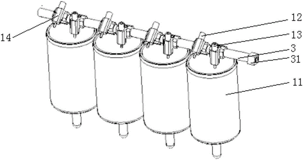
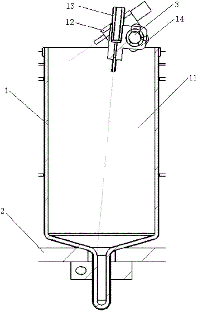
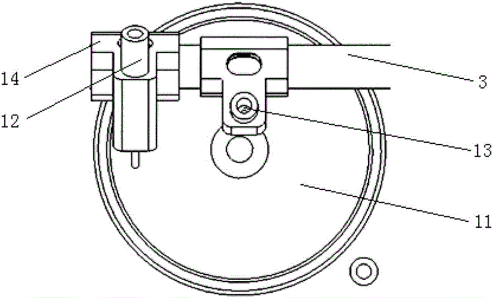
[0017] Such as Figure 1~3 As shown, the device for improving the concentration rate of the variable-diameter concentration cup of the present invention includes several concentration sub-devices 1, a support frame 2 and an air pipeline 3, and each concentration sub-device 1 includes a large-diameter upper part and a small-diameter lower part. Reduced-diameter concentrated cup 11, two blowing needle connectors 12, a first blowing needle 13 and a second blowing needle 14;

[0018] The bottom of the support frame 2 is horizontally provided with the same number of through holes as the variable diameter concentration cups 11. The support frame 2 can be in any form, and will not be repeated here. The lower small diameter of each variable diameter concentration cup 11 passes through the through holes. It is fixedly connected with the support frame 2, and the upper part of each variable-diameter concentration cup 11 is fixedly connected to the support frame 2, and the top of all the ...

Embodiment 2

[0025] The structure of this embodiment is basically the same as that of Embodiment 1, and the difference is that in this embodiment, the two blowing needle connectors 12, the first blowing needle 13 and the second blowing needle 14 in each concentration sub-device 1 of Embodiment 1 are Replaced with a movable blowing needle connecting frame 12 on the air pipeline 3 and a blowing needle 13 movably connected on the blowing needle connecting frame 12, when the solvent to be concentrated is in the large diameter of the variable-diameter concentration cup 11, the blowing needle The connecting frame 12 is fixedly arranged on the top of the variable-diameter concentration cup 11, and the air outlet direction of the blowing needle 13 is at an angle of 45° to any tangent direction of the inner wall cross section at 1-5 cm from the variable-diameter concentration cup 11 cup mouth. When being in the small diameter of the reduced-diameter concentration cup 11 , the blowing direction of th...


PUM

PropertyMeasurementUnit
The inside diameter ofaaaaaaaaaa

Abstract

The invention relates to a method and device for improving a concentration speed of a diameter-variable concentration cup. The method is characterized by comprising the following steps: (1) connecting one end of a gas path pipeline with a nitrogen gas source and pouring a solvent to be concentrated into the diameter-variable concentration cup; opening the nitrogen gas source and enabling nitrogen gas to enter the gas path pipeline; (2) when the solvent to be concentrated is located at a large opening diameter of the diameter-variable concentration cup, concentrating the solvent to be concentrated in a manner of forming an angle of 45 degrees between a gas outlet direction of a blowing needle and an any tangential direction of an inner wall cross section which is 1cm to 5cm far away from a cup opening of the diameter-variable concentration cup; (3) when the solvent to be concentrated is concentrated to a diameter-variable part of the diameter-variable concentration cup, requiring that gas blown out by a gas outlet of the blowing needle directly reaches the top of a small opening diameter of the diameter-variable concentration cup, so as to further concentrate the solvent to be concentrated; when the volume of the solvent to be concentrated is concentrated to be smaller than 1mL, finishing concentration of the solvent to be concentrated. The method and the device, provided by the invention, can be widely applied to experiments of concentrating solvents.

Description

technical field [0001] The invention relates to a method and a device for increasing the concentration rate of a variable-diameter concentration cup. Background technique [0002] When the nitrogen blowing concentrator is used for the concentration of a small volume of solvent, the gas outlet direction of the blowing needle is perpendicular to the liquid surface. The disadvantage of this concentration method is that as the liquid level drops, it is necessary to continuously lower the blowing needle or continuously increase the gas pressure to achieve The purpose of destroying the saturated vapor pressure on the surface of the liquid, but adjusting the height of the blowing needle requires manual on-duty, which consumes time and energy of the experimenter. [0003] When the existing nitrogen blowing concentrator is used for large-volume concentration, in order to increase the concentration rate, the air outlet of the blowing needle is generally blown out at a 45° angle along ...

Claims


Application Information

Patent Timeline
IPC IPC(8): G01N1/40
CPCG01N1/40
Inventor 田莉娟王斌王军许福斌
Owner BEIJING POLYTECH INSTR
Features
  • Generate Ideas
  • Intellectual Property
  • Life Sciences
  • Materials
  • Tech Scout
  • Unparalleled Data Quality
  • Higher Quality Content
  • 60% Fewer Hallucinations
Learn More