
In-situ high temperature micromechanics testing device in scanning electron microscope

An electron microscope and testing device technology, applied in measuring devices, using stable tension/pressure to test the strength of materials, scientific instruments, etc. It can solve the problems of large design volume and high weight, and achieve the effect of compact structure and convenient installation.

Pending Publication Date: 2017-02-01
ZHEJIANG UNIV +1
View PDF7 Cites 15 Cited by
  • Summary
  • Abstract
  • Description
  • Claims
  • Application Information

AI Technical Summary

Problems solved by technology

[0004] However, the current commercial in-situ stretching benches are designed to be large in size and high in weight, so they can only perform horizontal tensile tests at lower temperatures, and cannot perform high-temperature loads on samples in the scanning electron microscope sample chamber. Simultaneous realization of large-angle tilting for the study of EBSD crystal micro-orientation

Method used


Image

  • In-situ high temperature micromechanics testing device in scanning electron microscope
  • In-situ high temperature micromechanics testing device in scanning electron microscope
  • In-situ high temperature micromechanics testing device in scanning electron microscope

Examples


Embodiment 1

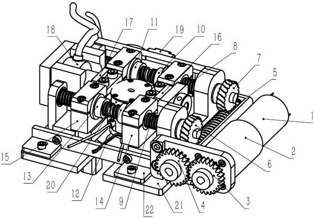
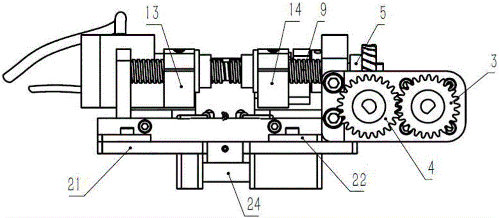
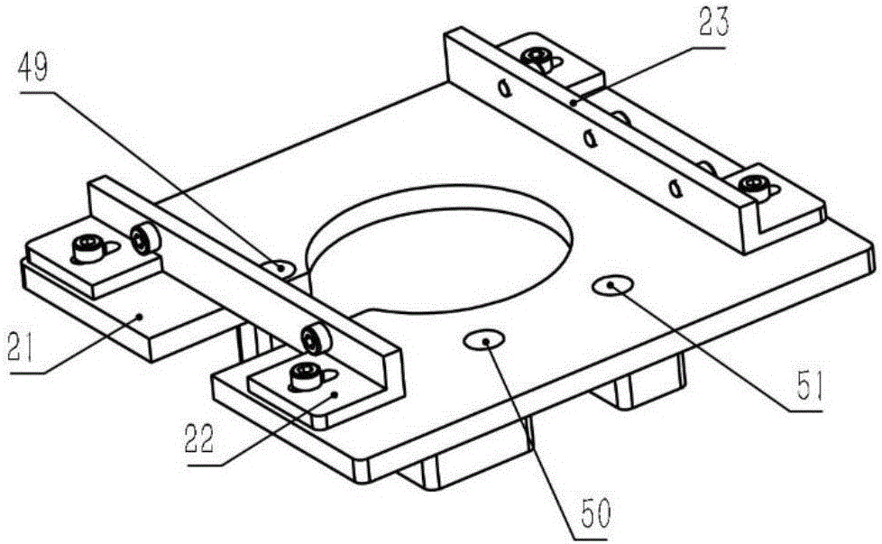
[0039] like Figures 1 to 11 , the present embodiment provides an in-situ high-temperature micromechanical testing device in a scanning electron microscope, including a control system 46, a tensile testing device, a heating device 20 and a fixing device. The tensile testing device is provided with an accommodating space, and the heating device 20 is arranged on In the accommodating space, the heating device 20 is used to provide a high temperature environment for the sample 30, and the tensile testing device applies a load to the sample 30, so that the sample 30 is tested under high temperature load; the tensile testing device and the heating device 20 The bottom ends are all connected with the fixture, and the bottom of the fixture is fixedly connected with the sample support frame 24 of the scanning electron microscope, that is, the whole micromechanical testing device is placed in the scanning electron microscope; the tensile testing device, the heating device 20 and the fix...

Embodiment 2

[0051] The basic structure of this embodiment is the same as that of Embodiment 1. The difference is that the in-situ high-temperature micromechanics testing device in the scanning electron microscope in this embodiment is a tilting in-situ tensile testing device, and the tilting original In the tensile testing device, the clamps arranged at the middle position on the top of the first sample clamp support frame 14 and the middle position on the top of the second sample clamp support frame 15 are respectively the first inclined clamp 47 and the second inclined clamp 48; The device is an inclined fixing device, and the inclined fixing device includes an inclined fixing seat 52, an inclined plate 53 and a supporting rib plate, and the inclined fixing seat 52 and the inclined plate 53 are arranged at an angle, and the inclined fixing seat 52 is fixedly connected with the sample support frame 24 of the scanning electron microscope , one end of the inclined fixing seat 52 is fixedly ...


PUM


Abstract

The invention discloses an in-situ high temperature micromechanics testing device in a scanning electron microscope. The device comprises a control system, an extension testing device, a heating device and a fixing device, wherein the extension testing device is provided with a containing space, and the heating device is arranged in the containing space; the bottom ends of the extension testing device and the heating device are respectively connected with the fixing device; the bottom end of the fixing device is fixedly connected with a sample support frame of the scanning electron microscope; the extension testing device, the heating device and the fixing device are all fixed in a chamber of the scanning electron microscope; the scanning electron microscope, the extension testing device and the heating device are respectively and electrically connected with the control system. The testing device provided by the invention is compact in structure, and can be conveniently installed in the microscope; by arranging the heating device, a test can be carried out under the condition of high temperature load; after the testing device is adopted, the in-situ imaging dynamic observation on a test sample under the actions of high temperature load and stress load is conveniently realized by using scanning electron beams, and the composition information spectrum and crystal structure information graph of the sample in the same observation micro area can be acquired at the same time.

Description

technical field [0001] The invention relates to the technical field of in-situ characterization of material microstructure and performance, in particular to an in-situ high-temperature micromechanical testing device in a scanning electron microscope. Background technique [0002] Scanning electron microscopy is one of the main tools for testing the microstructure of materials. It can measure the microstructure across scales from macro-to microscopic, and even nano-sized materials. It is an important means to reveal the microstructure of materials. [0003] In addition, the scanning electron microscope can be configured with an energy dispersive spectrometer (EDS) and an electron backscatter diffractometer (EBSD), which can establish a corresponding relationship between the microstructure of the material, the composition information of the microregion, and the crystallographic orientation. The scanning electron microscope has the characteristics of continuously adjustable mag...

Claims


Application Information

Patent Timeline
IPC IPC(8): G01N3/18
CPCG01N3/18G01N2203/0226G01N2203/0017G01N2203/0003G01N2203/0682G01N2203/0641G01N2203/06
Inventor 张跃飞王晋李吉学张泽
Owner ZHEJIANG UNIV
Learn More