Cepstrum linear potential energy function-based industrial image motion blur suppression method

A potential energy function and motion blur technology, applied in image enhancement, image analysis, image data processing, etc., can solve problems such as motion blur degradation, achieve the effect of improving quality and solving large-scale motion blur

Active Publication Date: 2017-02-01
宁波智能装备研究院有限公司
View PDF3 Cites 4 Cited by
  • Summary
  • Abstract
  • Description
  • Claims
  • Application Information

AI Technical Summary

Problems solved by technology

[0005] The purpose of the present invention is to propose an industrial image motion blur suppression method based on the cepstrum

Method used


Image

  • Cepstrum linear potential energy function-based industrial image motion blur suppression method
  • Cepstrum linear potential energy function-based industrial image motion blur suppression method
  • Cepstrum linear potential energy function-based industrial image motion blur suppression method

Examples


specific Embodiment approach 1

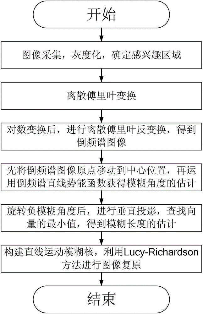
[0022] Specific implementation mode one: combine figure 1 The industrial image motion blur suppression method based on the cepstrum linear potential energy function of this embodiment is specifically prepared according to the following steps:

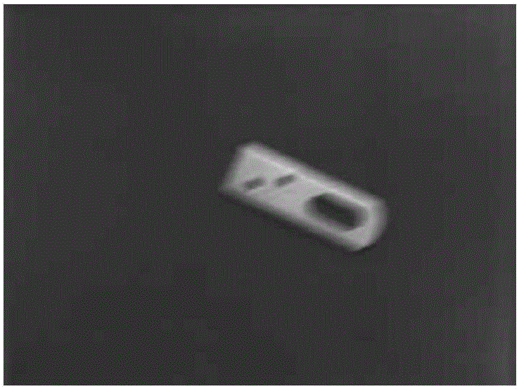
[0023] Step 1. Grayscale the motion blurred image collected by the industrial camera, and determine the region of interest as the ROI image for subsequent processing;

[0024] Step 2, carry out two-dimensional discrete Fourier transform to the ROI image obtained in step 1, solve the magnitude of each pixel in the transformed image, obtain the Fourier spectrum image;

[0025] Step 3, carry out natural logarithmic transformation to each pixel value of the Fourier spectrum image obtained in step 2 to obtain a logarithmic Fourier spectrum image, and perform two-dimensional discrete Fourier inversion on the obtained logarithmic Fourier spectrum image Transformation, solve the magnitude of each pixel in the transformed image, and obtain the ...

specific Embodiment approach 2

[0033] Specific embodiment two: the difference between this embodiment and specific embodiment one is: in step two, the mathematical expression of performing two-dimensional discrete Fourier transform on the ROI image obtained in step one is as follows:

[0034] F ( u , v ) = Σ x = 0 M - 1 Σ y = 0 N - 1 f ( x , y ) e - j 2 π ( u x / M + v y / N )

[0035] In the formul...

specific Embodiment approach 3

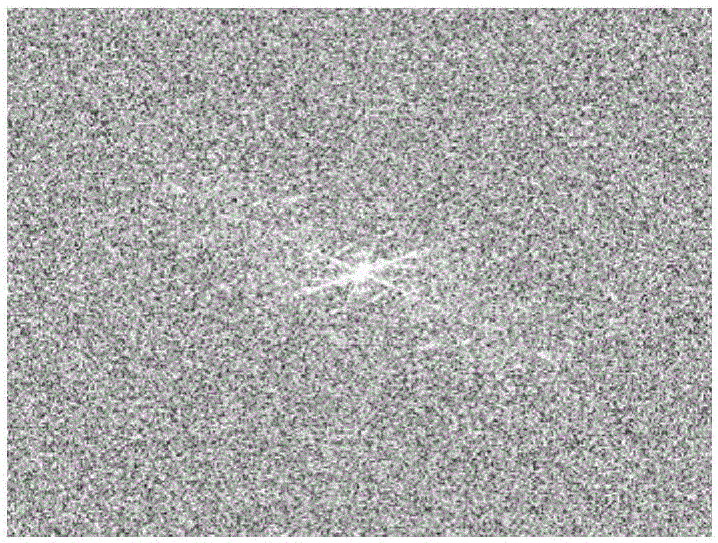
[0039] Specific implementation mode three: combination image 3 The difference between this embodiment and the specific embodiment one or two is: the specific process of obtaining the cepstrum image in step three is:

[0040] Step 31, performing natural logarithmic transformation on each pixel value of the Fourier spectrum image obtained in step 2, to obtain a logarithmic Fourier spectrum image;

[0041] Step 32, performing two-dimensional discrete Fourier inverse transform on the logarithmic Fourier spectrum image obtained in step 31, to obtain an inverse Fourier transform image;

[0042] Step 33: Solve the pixel amplitude of each pixel in the inverse Fourier transform image obtained in step 32 to obtain a cepstrum image; other steps and parameters are the same as those in Embodiment 1 or 2.


PUM


Abstract

The present invention relates to an industrial image motion blur suppression method, in particular, a cepstrum linear potential energy function-based industrial image motion blur suppression method. The objective of the invention is to solve the problem of motion blur degradation in an industrial imaging process. The method includes the following steps that: (1) a region of interest is determined; (2) a Fourier spectrum image is obtained; (3) a cepstrum image is obtained; (4) the estimated value phi <^> of the blur angle of an original ROI (region of interest) image is determined; (5) the estimated value lambda <^> of the blur length of the original ROI image is determined; and (6) a linear motion blur kernel is constructed for the blur angle phi <^> and blur scale lambda <^> of the ROI image which are obtained in the step (4) and the step (5), and image restoration is carried out through adopting Lucy-Richardson method, so that a clear ROI image is obtained. The method of the present invention is applied to the industrial image motion blur suppression field.

Description

technical field [0001] The invention relates to a motion blur suppression method of an industrial image, in particular to a motion blur suppression method of an industrial image based on a cepstrum linear potential energy function. Background technique [0002] The application of machine vision technology has significantly improved the flexibility and comprehensive performance of industrial automation inspection systems, and has been successfully applied in the fields of industrial component size measurement, industrial product information detection, feature recognition, etc., and has shown great development prospects. The machine vision detection system obtains industrial image information through optical sensors, and realizes the detection of industrial products or states based on image processing technology, thereby providing a basis for decision-making and control of subsequent production. [0003] Obtaining high-quality industrial image information is the key to machine...

Claims


Application Information

Patent Timeline
IPC IPC(8): G06T5/00
CPCG06T5/003G06T2207/20056
Inventor 高会军靳万鑫于金泳孙光辉杨宪强林伟阳李湛滕军
Owner 宁波智能装备研究院有限公司
Why Eureka
Try Eureka