Engine crankshaft storage device

A storage device and engine technology, applied in the direction of tool storage devices, manufacturing tools, etc., can solve the problems of increasing crankshaft production cost and increasing product scrap rate, and achieve the effects of low production cost, control product scrap rate, and reliable safety performance

Inactive Publication Date: 2017-02-08
周峰
View PDF7 Cites 4 Cited by
  • Summary
  • Abstract
  • Description
  • Claims
  • Application Information

AI Technical Summary

Problems solved by technology

Therefore, there are strict requirements for various production equipment and transfer equipment in the crankshaft production workshop. When the crankshaft is produced according to the production requirements, if the problem of wear and tear or even scrapping is caused by transfer stacking, it will undoubtedly increase the scrap rate of the product and greatly The increased production of crankshafts by Chen Ben

Method used


Image

  • Engine crankshaft storage device
  • Engine crankshaft storage device

Examples


Embodiment Construction

[0015] The present invention will be described in detail below with reference to the accompanying drawings and in combination with embodiments.

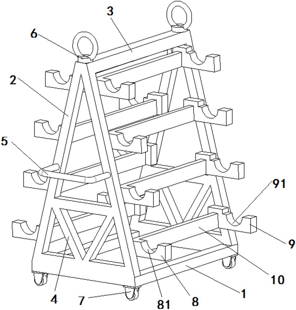
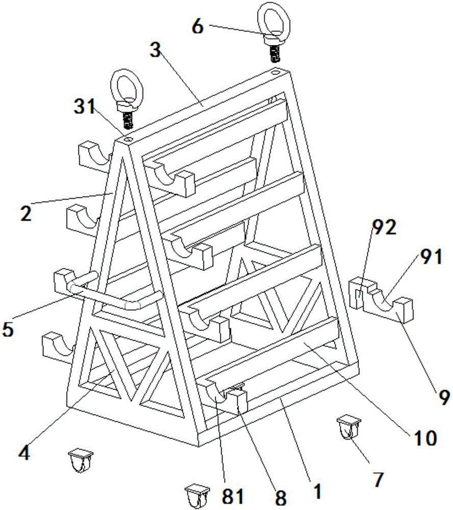
[0016] Such as Figure 1 to Figure 2 The engine crankshaft storage device shown includes a base 1, a support base 2, a connecting plate 3, a reinforcing rib 4, a handle 5, a suspension ring 6, casters 7, a backing plate 8, a sliding plate 9, and the left and right sides of a square base 1 A herringbone support seat 2 is arranged vertically, casters 7 are arranged around the bottom end, a triangular reinforcing rib 4 connected to the base 1 is arranged near the bottom end of the support seat 2, a U-shaped handle 5 is arranged horizontally in the middle, and a connecting foot is arranged at the top. There are connecting plates 3 on both sides, the left and right sides above the connecting plate 3 are provided with threaded holes 31, the threaded holes 31 are screwed with suspension rings 6, and several fixed plates 10 are vertically ar...


PUM


Abstract

The invention relates to an engine crankshaft storage device, comprising a base, support seats, a connecting plate, reinforcing ribs, a handle, a lifting ring, trundles, base plates and sliding plates; the herringbone support seats are vertically arranged at left and right sides of the square base, the positions of the support seats close to the bottom ends are provided with the triangular reinforcing ribs connected to the base, the top ends are provided with the connecting plate connected to both sides, threaded holes are arranged in left and right sides above the connecting plate, the lifting rings are disposed in the threaded holes, a plurality of fixing plates are vertically arranged between the left and right support seats, the base plates are horizontally fixed at one sides of the fixing plates, square grooves are arranged in the bottom ends of the left sides of the sliding plates, and the sliding plates are slidably mounted at the other sides of the fixing plates through the square grooves. The engine crankshaft storage device is simple in structure, low in manufacturing cost, more reliable in safety performance and higher in practicability and provides better protection for a crankshaft, an integral structural space of the device is effectively used, and a placing number of the device for the crankshaft is greatly increased.

Description

technical field [0001] The invention relates to the field of engines, in particular to an engine crankshaft storage device. Background technique [0002] The crankshaft cooperates with the connecting rod to change the gas pressure acting on the piston into rotational power, which is transmitted to the transmission mechanism of the chassis. At the same time, drive the gas distribution mechanism and other auxiliary devices, such as fans, water pumps, generators, etc. When working, the crank bearing is affected by gas pressure, inertial force and moment of inertia. The force is large and complex, and it bears the impact of alternating loads. At the same time, the crankshaft is a high-speed rotating part, and the crankshaft is required to have sufficient rigidity and strength. , has a good ability to withstand impact loads, wear resistance and good lubrication. Therefore, there are strict requirements for various production equipment and transfer equipment in the crankshaft pr...

Claims


Application Information

Patent Timeline
Patent Type & Authority Applications(China)
IPC IPC(8): B25H3/04
CPCB25H3/04
Inventor 周峰
Owner 周峰
Why Eureka
Try Eureka