

Flapping-wing flapping angle changing mechanism
A technology for changing angles and angles, which is applied in the field of flapping-wing aircraft variable flapping angle mechanisms, can solve the problems of heavy structural weight, low transmission efficiency, and short product life, and achieve the effects of reducing weight, improving reliability, and being easy to process
- Summary
- Abstract
- Description
- Claims
- Application Information
AI Technical Summary
Problems solved by technology
Method used
Image

Examples
Embodiment
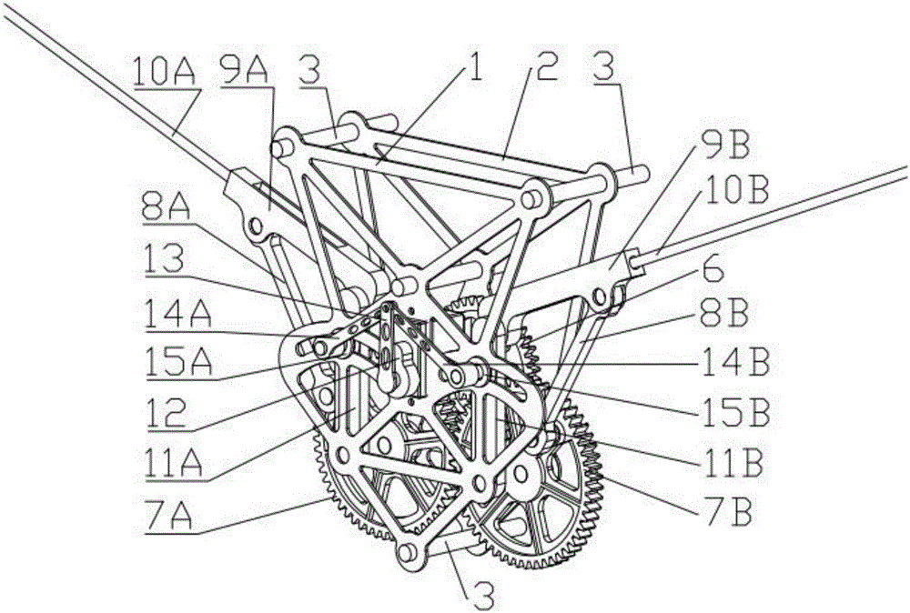
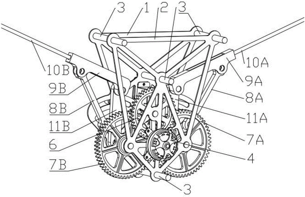
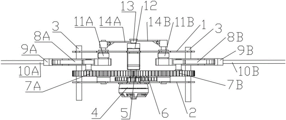
[0037] This example presents a flapping wing variable flapping angle mechanism, the front and rear substrates are 125mm high, 100mm wide, the connecting rod diameter of the fuselage is 5mm, the motor is Langyu 2204 brushless motor, the modulus of all gears is 1, and the number of motor gear teeth is 10. The number of teeth of the large and small gears on the intermediate gear is 42 and 15 respectively, the number of teeth of the driving gear is 55, the length of the flapping wing rod is 55mm, the length of the flapping wing swing arm is 65mm, the length of the flapping wing beam is 300mm, the length of the rotating base is 55mm, and the middle positioning rod is located at The position on the rotating base is 40mm from the bottom installation position, the length of the steering gear rod is 30mm, and the length of the steering gear rocker arm is 25mm. 1mm.
[0038] It has been verified by simulation that the flapping wing system of the device can realize a normal flapping move...
PUM
 Abstract
Description
Claims
Application Information