Rotary tooth

A technology of rotating seat and rotating axis, which is applied in the field of rotating gears, and can solve the problem that cutting teeth cannot use composite teeth

Active Publication Date: 2017-02-08
SOUTHWEST PETROLEUM UNIV +1
View PDF9 Cites 4 Cited by
  • Summary
  • Abstract
  • Description
  • Claims
  • Application Information

AI Technical Summary

Problems solved by technology

[0005] The purpose of the present invention is to provide a rotary tooth to solve the problem that the cutting teeth in the prior art cannot use composite teeth (such as PDC teeth), and at the same time, even if it uses cutting teeth consistent with the prior art (such as cemented carbide teeth) , the wear and wear passivation speed of the cutting teeth are also better

Method used


Image

  • Rotary tooth
  • Rotary tooth
  • Rotary tooth

Examples


Embodiment 1

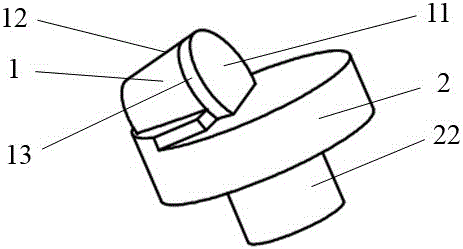
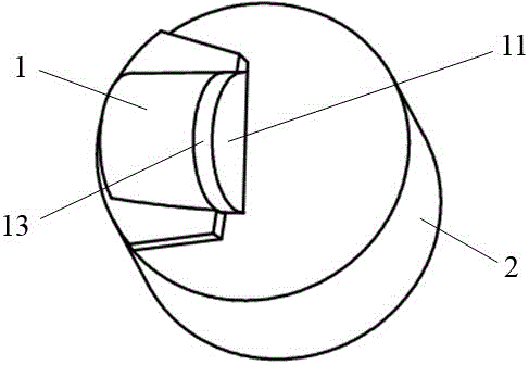
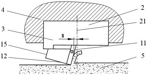
[0045] refer to Figure 1-6 As shown, a rotating tooth includes a cutting element 1 and a rotating seat 2, and the geometric center of the front cutting surface 11 of the cutting element 1 of the rotating tooth or the cutting surface 11 of the cutting element 1 of the rotating tooth is relative to the rotating seat 2 of the rotating tooth The rotation axis 21 of the cutting element 1 is offset, and the rear cutting surface 12 of the cutting element 1 of the rotating tooth or the geometric center O of the rear cutting surface 12 of the cutting element 1 is on the same side of the offset side. Alternatively, the cutting element 1 on the rotating tooth is a polycrystalline diamond composite (PDC tooth), polycrystalline diamond composite tooth, thermally stable polycrystalline diamond composite tooth, impregnated diamond tooth (block), cubic boron carbide, ceramic tooth, Or composite teeth made of polycrystalline diamond and impregnated diamond. As a further option, the cutting e...

Embodiment 2

[0047] This embodiment is basically the same as Embodiment 1, the difference is that: the drilling tool or rock-breaking tool 4 is a drill bit, the rotary teeth 3 are arranged on the cutting structure of the drill bit, and the rotary teeth 3 are formed by the rotary seat 2 and the cutting structure of the drill bit Rotationally connected, the rotating tooth 3 can rotate relative to the cutting structure on the drill bit. As an option, the rotary teeth 3 are arranged on the non-fixed cutting structure on the drill bit, such as being arranged on the cone 41 of the roller cone bit (such as Figure 5 ) or on the cone cutting structure of the composite drill bit (such as Figure 6 ). Alternatively, the rotary teeth 3 are arranged on a fixed cutting structure on the drill bit 4 (such as Figure 7 ). Further, the rotary teeth 3 are arranged on the radially inner third of the core area of ​​the drill bit. Furthermore, the rotation axis of the rotary seat of the rotary tooth near t...

Embodiment 3

[0049] refer to Figure 8 As shown, this embodiment is basically the same as Embodiment 1, the difference is that a locking structure 7 is provided between the rotary tooth 3 and the drilling tool or rock breaking tool 4 to limit the movement of the rotary tooth 3 in the direction of the rotation axis 21 . A retaining ring structure can be arranged between the rotary tooth 3 and the drilling tool or the rock-breaking tool 4 to prevent the rotary tooth 3 from moving along the direction of the rotation axis 21 or falling off along the axis. A threaded structure can be provided between them, and the rotating tooth 3 is limited in the rotating tooth hole of the drilling tool or the rock breaking tool 4 through the nut, so as to prevent the rotating tooth 3 from moving or falling off along the direction of the rotation axis 21. As a further option, ball locking is adopted between the rotary tooth 3 and the drilling tool or the rock breaking tool 4 (such as Figure 8 ).


PUM


Abstract

The invention discloses a rotary tooth and belongs to the technical field of drilling equipment of petroleum and natural gas, mine engineering, building foundation engineering construction, geology, hydrology and the like. The rotary tooth comprises a cutting element and a rotary seat, wherein a front cutting surface of the cutting element of the rotary tooth or the geometric center of the front cutting surface of the cutting element is deviated relative to a rotary axis of the rotary seat of the rotary tooth; a rear cutting surface of the cutting element of the rotary tooth or the geometric center of the rear cutting surface of the cutting element is located on the same side of the deviation direction of the front cutting surface; and the front cutting surface of the cutting element is close to the rotary axis of the rotary seat relative to the rear cutting surface. By adopting the rotary tooth provided by the invention, the problems of an existing drilling tool or rock crushing tool that a compound tooth (such as a PDC (Polycrystalline Diamond Compact) tooth) cannot be adopted or the compound tooth is easy to damage and the service life is short are solved; and meanwhile, when a cutting tooth (such as a hard alloy tooth) which is the same as that in the prior art is used, the abrasion of the cutting tooth and the abrasion passivation speed of the cutting tooth are relatively good.

Description

technical field [0001] The invention belongs to the technical field of drilling equipment such as petroleum and natural gas, mining engineering, building foundation engineering construction, geology, hydrology, etc., and particularly relates to a rotary tooth. Background technique [0002] Cutters are used in rock breaking tools, such as drill bits and other drilling tools, to break rocks or assist in breaking rocks. The interaction between cutting teeth and rock determines the working efficiency of cutting teeth in breaking rocks, and also determines the service life of cutting teeth. . The drill bit is a rock-breaking tool used in drilling engineering to directly break rocks and form wellbores. The drill bits used in drilling engineering today mainly include roller cone bits and PDC (polycrystalline diamond compact) bits. The cone on the roller cone bit forms a rotational connection with the bit body through the bearing system. When the drill bit is working, the rotation...

Claims


Application Information

Patent Timeline
Patent Type & Authority Applications(China)
IPC IPC(8): E21B10/43E21B10/55
CPCE21B10/43E21B10/55
Inventor 陈炼杨迎新谢宗亮任海涛
Owner SOUTHWEST PETROLEUM UNIV
Why Eureka
Try Eureka