Eureka AIR delivers breakthrough ideas for toughest innovation challenges, trusted by R&D personnel around the world.

Real-time simulation method for laser three-dimensional printing process

A 3D printing and real-time simulation technology, which is applied in special data processing applications, instruments, electrical digital data processing, etc., can solve problems such as long cycle, high cost, and process parameter failure, so as to reduce dependence, increase R&D speed, and reduce The effect of R&D costs

Active Publication Date: 2017-02-08
INST OF METAL RESEARCH - CHINESE ACAD OF SCI
View PDF5 Cites 15 Cited by
  • Summary
  • Abstract
  • Description
  • Claims
  • Application Information

AI Technical Summary

Problems solved by technology

Selecting and optimizing process parameters through traditional trial methods not only has a long cycle and high cost, but also the obtained process parameters have great limitations (the process parameters obtained by changing the shape and size may fail)

Method used


Image

  • Real-time simulation method for laser three-dimensional printing process
  • Real-time simulation method for laser three-dimensional printing process
  • Real-time simulation method for laser three-dimensional printing process

Examples


Embodiment 1

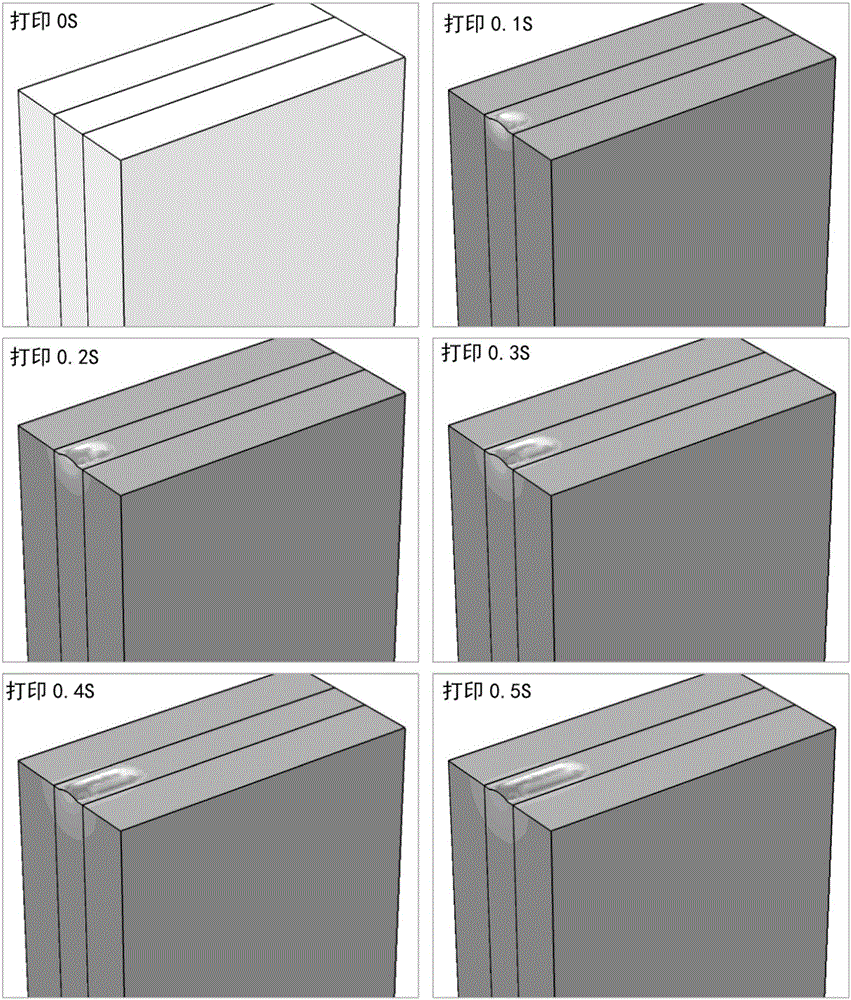
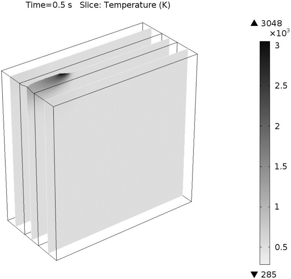
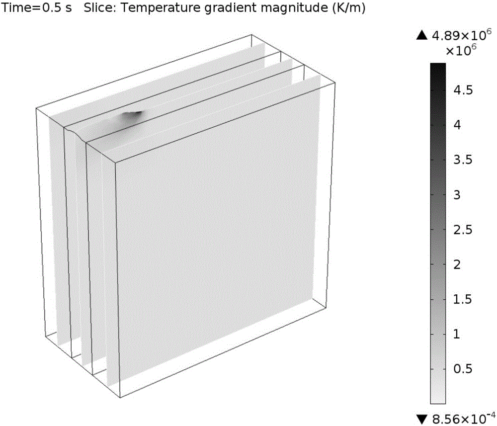
[0086] Taking superalloy DD5 as an example, laser 3D printing with coaxial powder feeding is carried out on a substrate with a length of 2 cm × width of 1 cm × height of 2 cm. The laser power is 1500W, the laser absorption rate is set to 15%, and the spot radius is set to 0.7mm. The powder feeding rate is 10g / min, and the powder is distributed in a circle with a radius of 1.5mm. During the printing process, the laser scanning speed is 600mm / min. Using the calculation method introduced above, the shape and size change map of the substrate during the printing process can be obtained, as shown in figure 1 shown. exist figure 1 The shape and size changes from 0s, 0.1s, 0.2s, 0.3s, 0.4s to 0.5s are shown in . The temperature field distribution can be obtained by taking the profile at 0.5s from the calculation results, such as figure 2 shown. Taking the profile at 0.5s in the calculation results can also get the distribution of the temperature gradient, such as image 3 show...

Embodiment 2

[0088] Taking the superalloy DD5 as an example, laser 3D printing of powder coating is carried out on a substrate with a length of 2cm x width of 1cm x height of 2cm. The laser power is 1500W, the laser absorption rate is set to 15%, and the spot radius is set to 0.7mm. The powder coating thickness is 0.2mm. During the printing process, the laser scanning speed is 1200mm / min. Similarly, the shape and size change map of the substrate during the printing process can be obtained through calculation, such as Figure 4 shown. exist Figure 4 The shape and size changes from 0s, 0.05s, 0.10s, 0.15s, 0.20s to 0.25s are shown in .

Embodiment 3

[0090] Taking superalloy DD5 as an example, laser 3D printing with coaxial powder feeding is carried out on a substrate with a length of 1.5 cm × width of 1 cm × height of 2 cm. The laser power is 1500W, the laser absorption rate is set to 15%, and the spot radius is set to 0.7mm. The powder feeding rate is 10g / min, and the powder is distributed in a circle with a radius of 1.5mm. During the printing process, the laser scanning speed is 600mm / min, and the distance between adjacent passes is 1.05mm. When the shape factor is not added, the calculation result is as follows Figure 5 shown. After adding the shape factor, the calculation result is as follows Figure 6 shown. Figure 5 There are many abrupt sharp corners in , and this phenomenon is well suppressed after adding the shape factor (such as Figure 6 ).


PUM

PropertyMeasurementUnit
radiusaaaaaaaaaa
thicknessaaaaaaaaaa

Abstract

The invention discloses a real-time simulation method for a laser three-dimensional printing process, and belongs to the field of laser forming manufacturing and rapid prototyping. The method describes distribution state of powder, computes energy requirements of a powder fusing process, and thus acquires variations of a shape and a size of a component during a printing process. According to the method, with the aid of computational simulation, the laser three-dimensional printing process can be simulated in real time, and information, such as a temperature field, during a laser three-dimensional printing process can be acquired. Existing laser forming technology screening methods depend on a large amount of experimental data, and are long in experimental period and high in cost. The method provided by the invention can simulate the laser three-dimensional printing processes of different technological parameters in real time. The technological parameters are prejudged before experimental processing to screen out the appropriate technological parameters. According to the method provided by the invention, the development speed of the laser forming technology can be greatly improved, and the development cost can be reduced.

Description

[0001] Technical field: [0002] The invention relates to the technical field of laser forming manufacturing and rapid prototyping, in particular to a real-time simulation method of a laser 3D printing process. [0003] Background technique: [0004] 3D printing originated from rapid manufacturing technology. With the rise of 3D printing technology for metal materials, 3D printing has received widespread attention worldwide. Compared with traditional casting technology, 3D printing does not need to prepare molds, which shortens the development cycle of parts. Compared with forgings, 3D printing can realize complex shape structures while providing comparable mechanical properties. More importantly, 3D printing fills the gap of traditional processing technology when preparing complex structural parts such as mesh. [0005] Even though 3D printing has many advantages, the formulation of its process parameters is still a big problem. Similar to traditional casting and forging, e...

Claims


Application Information

Patent Timeline
Patent Type & Authority Applications(China)
IPC IPC(8): G06F17/50
CPCG06F30/23
Inventor 周亦胄王国伟梁静静杨彦红金涛
Owner INST OF METAL RESEARCH - CHINESE ACAD OF SCI
Why Eureka
Eureka Blog
Learn More