Tower stay wire bending device suitable for large bending force

A bending device and high bending force technology, applied in the direction of overhead line/cable equipment, etc., can solve the problems of affecting the safety of human body and gasket line equipment, uneven force on contact parts, poor matching of connected parts, etc., to achieve accurate Dense and reliable fixation, improved safety and reliability, and high precision

Active Publication Date: 2017-02-08
SHANGHE COUNTY POWER SUPPLY CO STATE GRID SHANDONG ELECTRIC POWER CO +1
View PDF4 Cites 2 Cited by
  • Summary
  • Abstract
  • Description
  • Claims
  • Application Information

AI Technical Summary

Problems solved by technology

[0002] In the prior art, the wire bending equipment such as utility poles usually adopts manual bending and hand-held tools for bending. The defects of this bending method and structure are that the labor intensity of the operator is high, the work efficiency is low, and the bending and forming Poor accuracy and poor matching between the connected parts durin

Method used


Image

  • Tower stay wire bending device suitable for large bending force
  • Tower stay wire bending device suitable for large bending force
  • Tower stay wire bending device suitable for large bending force

Examples


Embodiment Construction

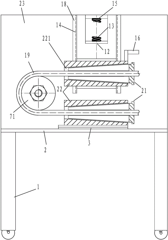
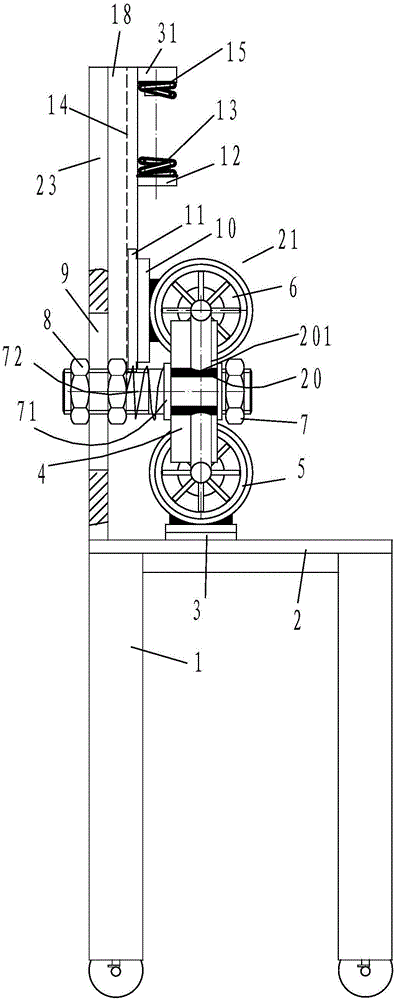
[0032] In order to better understand the present invention, the implementation manner of the present invention will be explained in detail below in conjunction with the accompanying drawings.

[0033] Such as Figure 1 to Figure 4 As shown, a tower rod stay wire bending device suitable for large bending force includes a connected vertical support 1 and a horizontal support 2. The horizontal support 2 is provided with a support structure under the stay wire. It is equipped with a stay wire support structure and a stay wire bending positioning structure. The stay wire bending positioning structure includes a fixed shaft 7. The support structure under the pull wire is matched, the other end of the pull wire is matched with the support structure on the pull wire. Bend the pull wire at the bending part of the pull wire into a desired arc shape. The lower part of the vertical support is provided with universal moving wheels.

[0034] The support structure on the pull wire is conn...


PUM


Abstract

The invention discloses a tower stay wire bending device suitable for large bending force. The tower stay wire bending device comprises a vertical support and a horizontal support. The horizontal support is provided with a stay wire lower clamp structure. The vertical support is provided with a stay wire upper clamp structure and a stay wire bending and positioning structure. The stay wire bending and positioning structure comprises a fixing shaft and a stay wire positioning sleeve. One end of a stay wire is matched with the stay wire lower clamp structure, and the other end is matched with the stay wire upper clamp structure. The stay wire upper clamp structure is connected with a slide block. The vertical support is provided with vertical guide rails. The slide block is matched with the grooves in the vertical guide rails. The stay wire lower clamp structure and the stay wire upper clamp structure comprise a fixing sleeve and a hollow shaft. The fixing sleeve is provided with an axial conical hole. The hollow shaft is provided with an external conical surface and an internal cylindrical hole which are matched with the conical hole. The hollow shaft is provided with multiple open slots which are open along the axial small end on the cone. The external conical surface of the hollow shaft and the small end of the conical hole are close to the stay wire bending and positioning structure. The vertical support is provided with an upper limiting structure between the vertical guide rails.

Description

technical field [0001] The invention relates to the technical field of cable bending processing equipment, in particular to a tower rod cable bending device suitable for large bending force. Background technique [0002] In the prior art, the wire bending equipment such as utility poles usually adopts manual bending and hand-held tools for bending. The defects of this bending method and structure are that the labor intensity of the operator is high, the work efficiency is low, and the bending and forming Poor accuracy and poor matching between the connected parts during installation and use will easily cause uneven force on the contact parts, affect subsequent use, local degeneration and damage, and even affect the safety of the person, gasket, circuit and equipment used. Since the backguy has a relatively large rebound force after being bent, it is unsafe to rebound easily and cause injury to the operator during operation. Contents of the invention [0003] The object of...

Claims


Application Information

Patent Timeline
IPC IPC(8): H02G1/02
CPCH02G1/02
Inventor 党法权杨叶红
Owner SHANGHE COUNTY POWER SUPPLY CO STATE GRID SHANDONG ELECTRIC POWER CO
Why Eureka
Try Eureka