
Control method of frequency converter and control device

A control method and control device technology, applied in the field of frequency converters, can solve problems such as frequency converter overcurrent and equipment shutdown, and achieve the effects of preventing circuit failures, reducing the number of shutdowns, and reducing output current

Inactive Publication Date: 2017-02-08
LS INDAL SYST WUXI
View PDF3 Cites 7 Cited by
  • Summary
  • Abstract
  • Description
  • Claims
  • Application Information

AI Technical Summary

Problems solved by technology

[0005] Aiming at the problems existing in the prior art, the present invention provides a control method and a control device for a frequency converter, so as to solve the technical problem in the prior art that an overcurrent occurs when the frequency converter is running at high speed and the equipment shuts down

Method used


Image

  • Control method of frequency converter and control device
  • Control method of frequency converter and control device
  • Control method of frequency converter and control device

Examples


Embodiment 1

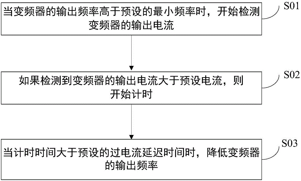
[0035] In order to solve the above problems, Embodiment 1 of the present invention provides a control method of a frequency converter, the steps are as follows figure 2 shown, including the following steps:

[0036] Step S01, when the output frequency of the frequency converter is higher than the preset minimum frequency, start to detect the output current of the frequency converter;

[0037] Step S02, if it is detected that the output current of the frequency converter is greater than the preset current, start timing;

[0038] Step S03, when the timing time is greater than the preset overcurrent delay time, reduce the output frequency of the frequency converter.

[0039] According to the size of the output current of the inverter, reduce the output frequency of the inverter to reduce the slip between the inverter and the motor. After the slip of the motor is reduced, the output current of the inverter will also decrease to prevent overcurrent faults.

[0040] It should be ...

Embodiment approach

[0047] The relevant parameters involved in the control process, the corresponding set values ​​and the description of the setting range are shown in Table 1:

[0048]

[0049] Table I

[0050] The parameter AP-1 is used to indicate the selection of the overcurrent prevention function. When AP-1 is set to 1, the overcurrent prevention function is enabled; when AP-1 is set to 0, the overcurrent prevention function is not enabled. When the output frequency of the inverter is 60Hz higher than the minimum frequency for overcurrent prevention set by AP-2, the overcurrent prevention function starts to act, that is, when the output frequency of the inverter is higher than the minimum frequency for overcurrent prevention set by AP-2 , start to detect the output current of the inverter, and judge whether the output current of the inverter is greater than the preset current, and also judge whether the current delay time is satisfied.

[0051] Parameter AP-3 is the delay time for prev...

Embodiment 2

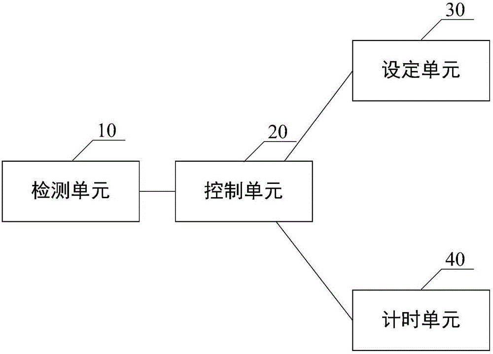
[0055] Embodiment 2 of the present invention also provides a control device for a frequency converter, the schematic diagram of which is shown in image 3 shown, including:


PUM


Abstract

The invention discloses a control method of a frequency converter and a control device. The control method of the frequency converter comprises the following steps of when an output frequency of the frequency converter is higher than a preset minimum frequency, beginning to detect an output current of the frequency converter; if the output current of the frequency converter is detected to be greater than a preset current, beginning to carry out timekeeping; when timing time is greater than preset overcurrent delay time, reducing the output frequency of the frequency converter. The invention also provides a corresponding control device of the frequency converter. When the output current of the frequency converter is too large, the output frequency of the frequency converter is reduced to a reference frequency. A slip frequency of the frequency converter and a motor is reduced so as to decrease the output current of the frequency converter. A circuit fault phenomenon caused by an overcurrent is prevented. Therefore, shutdown times of the device because of the overcurrent can be reduced and problems of resource and time wastes caused by repeated shutdown are solved.

Description

technical field [0001] The invention relates to the technical field of frequency converters, in particular to a control method and a control device for frequency converters. Background technique [0002] The frequency converter uses frequency conversion technology and microelectronics technology to control the power control equipment of the AC motor by changing the frequency of the motor's working power supply. It can adjust the voltage and frequency of the output power supply and provide the required power supply voltage according to the actual needs of the motor. And then achieve the purpose of energy saving and speed regulation. With the continuous improvement of industrial automation, frequency converters have also been widely used. [0003] When the inverter is applied to an industrial washing machine, it needs to run at high speed to realize the dehydration action of the industrial washing machine. The dehydration action of the industrial washing machine is completed...

Claims


Application Information

Patent Timeline
Patent Type & Authority Applications(China)
IPC IPC(8): H02P27/04
Inventor 李可喜
Owner LS INDAL SYST WUXI
Learn More