A hanging parasol
A parasol and hanging technology, applied in the field of parasols, can solve the problems of inconvenient use, laborious operation, laborious operation, etc., and achieve the effects of facilitating retracting and unwinding of the traction rope, simple and convenient operation, and not easy to entangle.
- Summary
- Abstract
- Description
- Claims
- Application Information
AI Technical Summary
Problems solved by technology
Method used
Image
Examples
Embodiment 1
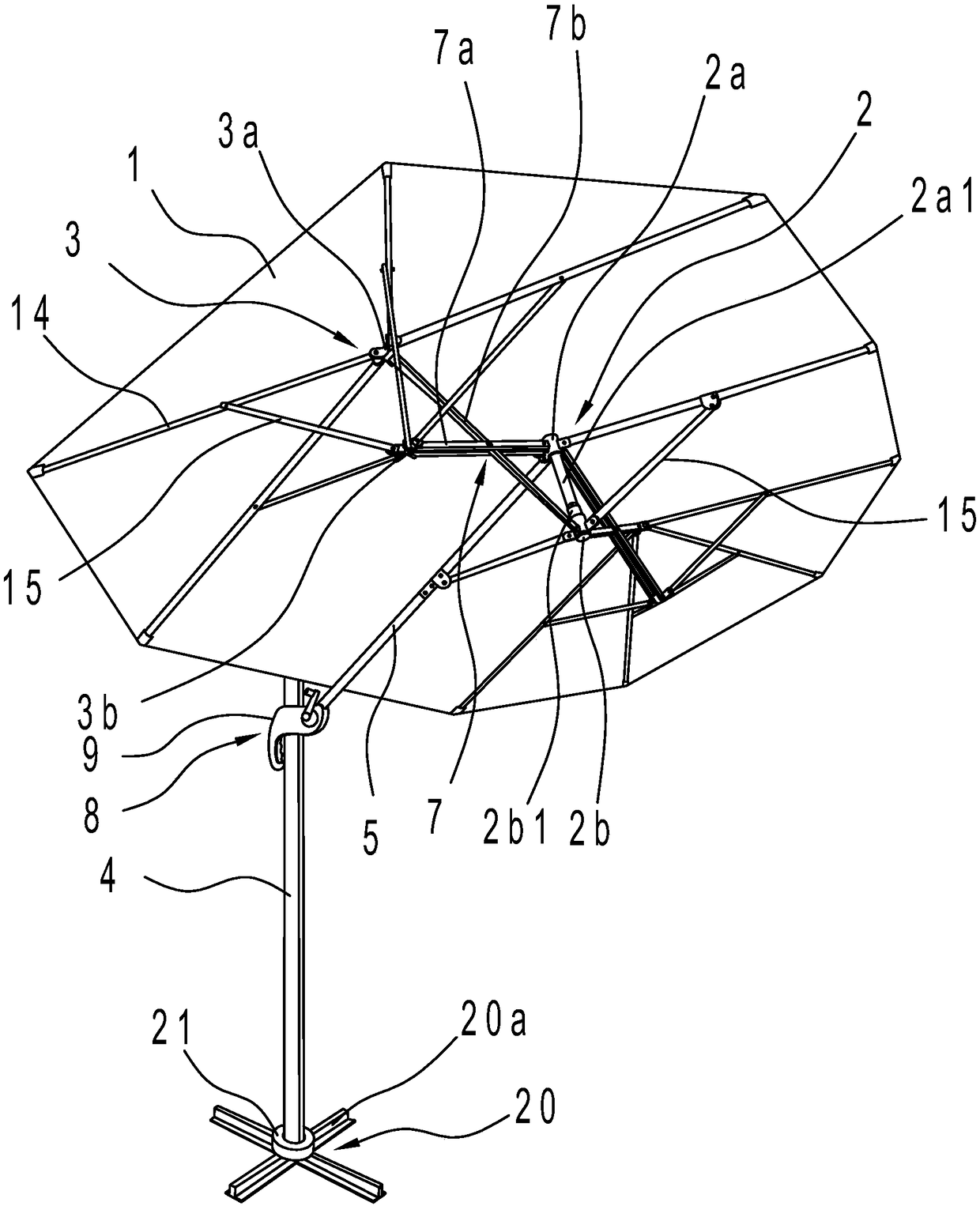
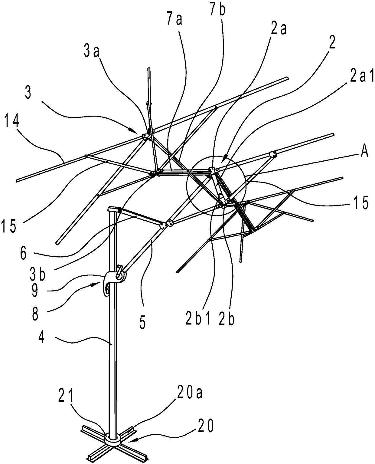
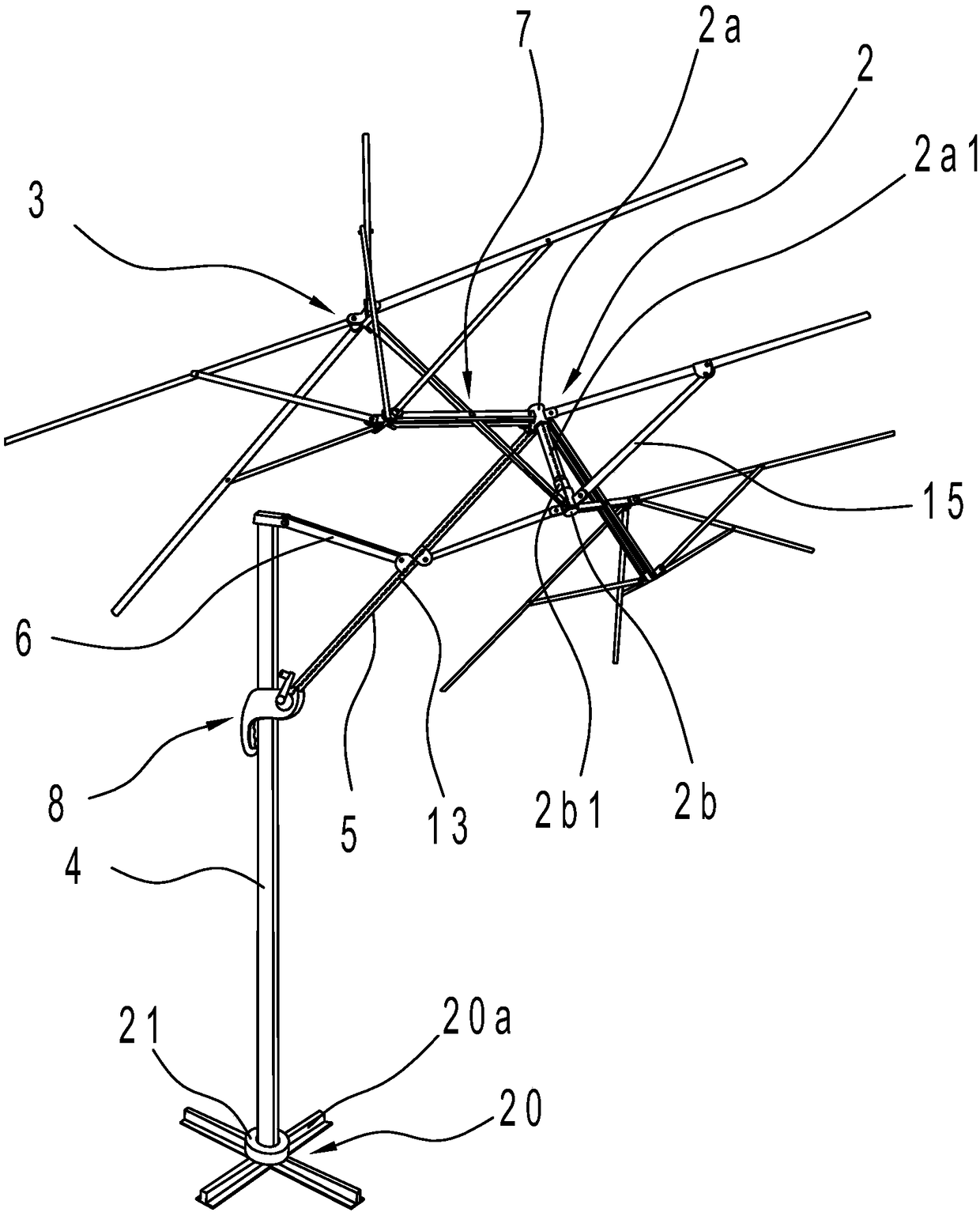
[0027] Such as figure 1 , figure 2 and image 3 As shown, the hanging parasol includes an umbrella surface 1, a main umbrella frame 2, an auxiliary umbrella frame 3, a vertical rod 4, a diagonal rod 5 and a diagonal rod 6, and the umbrella surface 1 is covered on the main umbrella frame 2 and the auxiliary umbrella frame 3. Specifically, both the main umbrella frame 2 and the secondary umbrella frame 3 are connected to the umbrella surface 1 through several long ribs 14 . The hanging sunshade also includes a base 20 and a turntable 21 arranged on the base 20 , the turntable 21 can rotate on the base 20 with its central axis as the axis, and the lower end of the pole 4 is rotatably connected with the turntable 21 . Because the vertical pole 4 is fixed on the rotating disk 21, by rotating the rotating disk 21, the rotation of the hanging sunshade can be realized, which is convenient for the user to adjust the sunshade range of the hanging sunshade and improve its sunshading e...
Embodiment 2
[0038] Such as Figure 8 As shown, in the present embodiment, the specific structure of the hanging parasol is basically the same as that of Embodiment 1, the difference is that the sliding locator 8 adopts the following structure: the sliding locator 8 includes a handle 9 arranged on the pole 4, The handle 9 includes a handshake part 9a and a housing 9b that is sleeved outside the pole 4 and can move back and forth along the axis of the pole 4. A number of positioning holes 4a are opened on the pole 4 from top to bottom, and the handshake part 9a is equipped with positioning pins. 22 and the return spring 11 that makes the positioning pin 22 have a tendency to be inserted into the positioning hole 4a. One end of the return spring 11 leans against the inner wall of the handshake portion 9a, and the other end leans against the positioning pin 22. The bottom end of the oblique rod 5 is hinged on the shell on 9b.
PUM
 Abstract
Description
Claims
Application Information
 - R&D
- Intellectual Property
- Life Sciences
- Materials
- Tech Scout
- Unparalleled Data Quality
- Higher Quality Content
- 60% Fewer Hallucinations
Browse by: Latest US Patents, China's latest patents, Technical Efficacy Thesaurus, Application Domain, Technology Topic, Popular Technical Reports.
© 2025 PatSnap. All rights reserved.Legal|Privacy policy|Modern Slavery Act Transparency Statement|Sitemap|About US| Contact US: help@patsnap.com


