A semi-automatic profiling pipe intersecting line cutting equipment capable of processing grooves

An intersecting wire cutting and semi-automatic technology, applied in metal processing equipment, welding equipment, metal processing, etc., can solve the problems of heavy processing workload, low production efficiency, simple function, etc., achieve low cost, simple structure, and ensure processing quality effect

Active Publication Date: 2018-08-31
JIANGSU SANYI BUILDING TECH
View PDF5 Cites 0 Cited by
  • Summary
  • Abstract
  • Description
  • Claims
  • Application Information

AI Technical Summary

Problems solved by technology

The first type of manual cutting has the advantages of flexibility, convenience, simple operation, and low cost, but manual cutting has poor quality, large dimensional errors, large material waste, and large follow-up processing workload. At the same time, the working conditions are harsh, labor intensity is high, and production efficiency is low.
The second type of semi-automatic cutting machine cutting, although it reduces the labor intensity of workers, its function is simple, and it is only suitable for cutting parts with more regular shapes.
However, due to the relatively high price and maintenance costs of the intersecting wire cutting machine, considering the cost and benefit, some small and medium-sized enterprises in our country and even some large enterprises currently use manual cutting and semi-automatic cutting.

Method used


Image

  • A semi-automatic profiling pipe intersecting line cutting equipment capable of processing grooves
  • A semi-automatic profiling pipe intersecting line cutting equipment capable of processing grooves
  • A semi-automatic profiling pipe intersecting line cutting equipment capable of processing grooves

Examples


Embodiment Construction

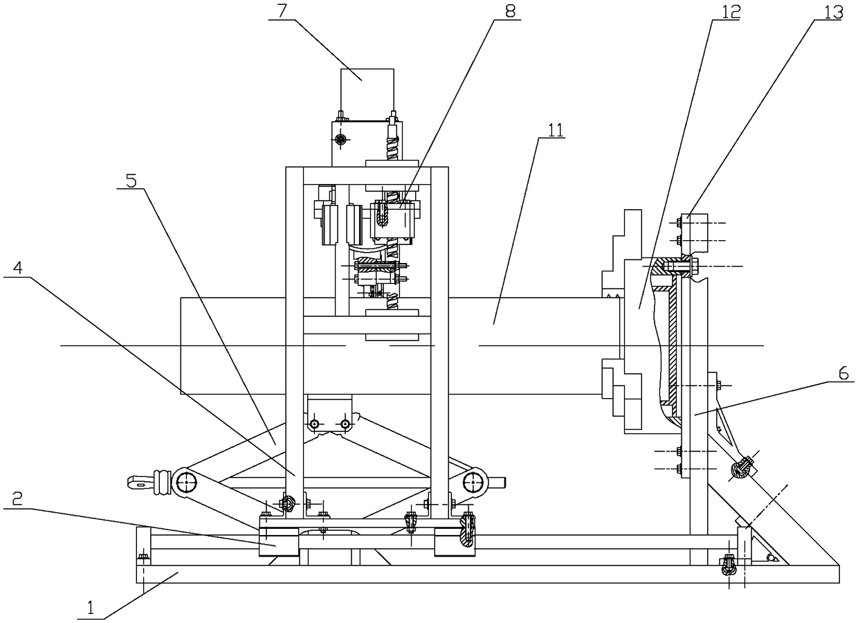
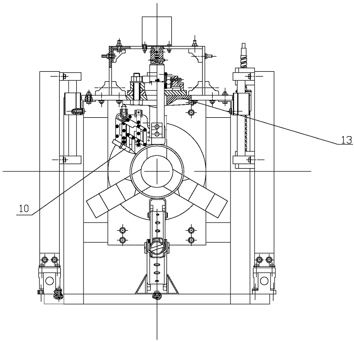
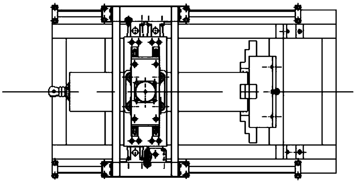
[0029] Such as Figure 1 to Figure 5 As shown, a semi-automatic profiling pipeline intersecting line cutting device capable of processing grooves of the present invention includes a base 1, a fixed bracket 6 on the base 1, a moving bracket 4 and a fixing bracket on the moving bracket 4. The moving bracket 4 is moved on the base 1 by a moving device, the moving device includes a lead screw nut and a leading screw, the moving bracket 4 is connected with the leading screw nut, and the moving bracket 4 is driven to move by the rotation of the leading screw, and the moving bracket is installed on the slider The slider is set on the sliding guide rail 2, the motor 7 is installed on the fixed frame, the motor 7 is connected with the main shaft 8 installed on the fixed frame, the main shaft 8 is driven by the motor 7, and the main shaft 8 passes through the moving The profiling cam component 13 on the support 4, the profiling cam component 13 is installed on the mobile support 4, the ...


PUM


Abstract

The invention discloses semi-automatic profiling pipeline intersecting curve flame cutting equipment capable of machining grooves. The semi-automatic profiling pipeline intersecting curve flame cutting equipment comprises a base, a fixed support, a movable support and a fixed frame. The movable support moves on the base through a moving device. The fixed frame is provided with a spindle. The spindle is driven by a motor to rotate. The spindle penetrates through a profiling cam component. The tail end of the connecting plate spindle is fixedly connected with a parallelogram connecting rod through a connecting plate. One vertex of the parallelogram connecting rod is connected with a profiling push rod, and one end of the profiling push rod abuts against a profiling contour. One side of a guide groove of the parallelogram connecting rod extends to form the guide groove, and a pin shaft is arranged in the guide groove. The pin shaft is fixed to a cam push rod. One end of the cam push rod is fixed to the connecting plate, and the other end of the cam push rod abuts against a cam contour. The parallelogram connecting rod is hinged to a cutting gun fixed rod. By means of the semi-automatic profiling pipeline intersecting curve flame cutting equipment, production cost can be greatly reduced through the profiling under the condition of guaranteeing machining quality, and meanwhile production efficiency is improved obviously. Moreover, cutting equipment is simple in structure and low in cost.

Description

technical field [0001] The invention relates to a semi-automatic profiling pipe intersecting line cutting device capable of processing grooves, and belongs to the field of mechanical processing industry and its equipment. Background technique [0002] Intersecting wire cutting equipment is widely used in the cutting and processing of pipeline structural parts in construction, chemical industry, shipbuilding, mechanical engineering, metallurgy, electric power and other industries. Intersecting line cutting equipment generally includes three parts: cutting head, claw plate, and roller frame. The cutting head has the functions of walking the intersecting line track and cutting. The mechanism has high requirements for operating sensitivity and accuracy, so the structure is relatively complicated. It is the core part of the intersecting wire cutting equipment. [0003] At present, in the mechanical processing process, there are three types of existing pipe cutting methods: manua...

Claims


Application Information

Patent Timeline
Patent Type & Authority Patents(China)
IPC IPC(8): B23K31/10B23K101/06
CPCB23K31/10B23K2101/06
Inventor 李滨城索鑫宇耿浩涵
Owner JIANGSU SANYI BUILDING TECH
Why Eureka
Try Eureka