Workpiece fixture for numerically-controlled machine tool

A workpiece fixture and CNC machine tool technology, applied in the direction of manufacturing tools, metal processing machinery parts, clamping, etc., can solve the problems of increasing production costs and maintenance costs, intensifying machining operations, and reducing processing efficiency, etc., to achieve flexible assembly Clamping scheme, enhanced processing range, and the effect of stereotaxic positioning

Inactive Publication Date: 2017-02-15
昆山西诺巴精密模具有限公司
View PDF5 Cites 4 Cited by
  • Summary
  • Abstract
  • Description
  • Claims
  • Application Information

AI Technical Summary

Problems solved by technology

At present, in the processing and production of molds with tooling, the tooling and the mold cannot be rotated after being fixed. When processing the mold, when it involves processing of different surfaces and angles, it must be realized by adjusting the tool position of the machine tool. At the same time, it is necessary to adjust the positioning angle of the mold, which intensifies the cumbersomeness of the machining operation and reduces the processing efficiency; moreover, in the process of mold processing, the processing is relatively complicated, and frequent adjustment of the tool position of the machine tool is likely to cause an increase in the processing error rate, resulting in product failure. Decreased quality, increased scrap rate
On the other hand, the size of the working surface of the existing tooling is basically fixed, and a tooling is only suitable for processing molds that match the size of the working surface. Factories often need to equip a large number of tooling for production and processing, which inevitably increases the Production costs and maintenance costs

Method used


Image

  • Workpiece fixture for numerically-controlled machine tool
  • Workpiece fixture for numerically-controlled machine tool
  • Workpiece fixture for numerically-controlled machine tool

Examples


Embodiment 1

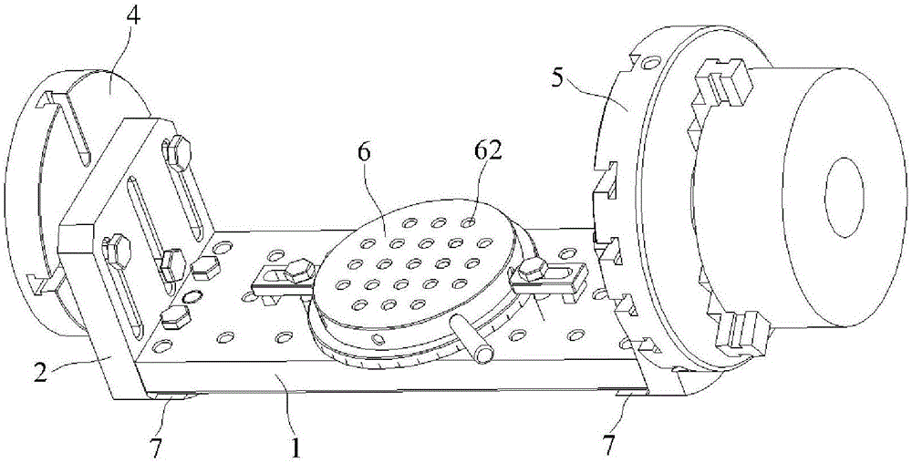
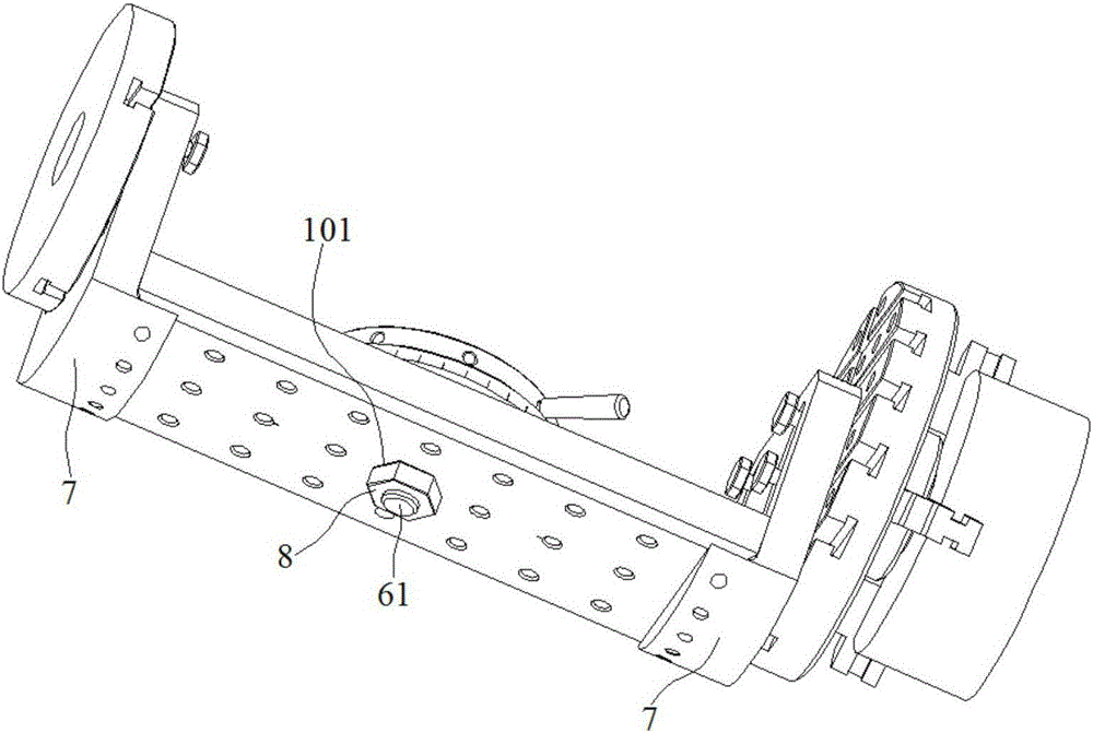
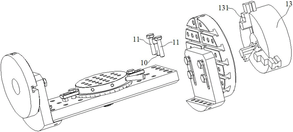
[0027] Embodiment 1: A workpiece fixture for a numerically controlled machine tool, comprising a base plate 1, a left side plate 2, a right side plate 3, a left connecting plate 4, a right connecting plate 5, a ball lock clamping mechanism and a method installed on the upper surface of the base plate 1 The blue plate 6, the lower part of the left side plate 2 and the right side plate 3 has a bottom convex strip 7, the base plate 1 is located between the left side plate 2 and the right side plate 3, and the two ends of the base plate 1 are respectively installed on the left side The upper surface of the bottom convex strip 7 of the plate 2 and the right side plate 3 respectively, the left connecting plate 4 is installed on the surface opposite to the left side plate 2 and the base plate 1, and the right connecting plate 5 is installed on the right side plate 3 and the base plate 1 opposing surfaces;

[0028] A central bolt 61 is fixed at the bottom of the flange 6, and a centra...

Embodiment 2

[0034] Embodiment 2: A workpiece fixture for a numerically controlled machine tool, comprising a base plate 1, a left side plate 2, a right side plate 3, a left connecting plate 4, a right connecting plate 5, a ball lock clamping mechanism and a method installed on the upper surface of the base plate 1 The blue plate 6, the lower part of the left side plate 2 and the right side plate 3 has a bottom convex strip 7, the base plate 1 is located between the left side plate 2 and the right side plate 3, and the two ends of the base plate 1 are respectively installed on the left side The upper surface of the bottom convex strip 7 of the plate 2 and the right side plate 3 respectively, the left connecting plate 4 is installed on the surface opposite to the left side plate 2 and the base plate 1, and the right connecting plate 5 is installed on the right side plate 3 and the base plate 1 opposing surfaces;

[0035] A central bolt 61 is fixed at the bottom of the flange 6, and a centra...


PUM


Abstract

The invention discloses a workpiece fixture for a numerically-controlled machine tool. A center bolt is fixed to the bottom of a flange plate of the workpiece fixture. A center through hole is formed in a center area of a base plate. The center bolt on the flange plate is embedded into the center through hole of the base plate. A nut is located on the lower surface of the base plate and is installed at the tail end of the center bolt. A ball lock clamping mechanism is installed on the upper surface of the flange plate and further comprises a bottom plate, a base plate body, a left positioning plate, a right positioning plate, a U-shaped elastic sheet, a wedge block with a first through hole, a left to-be-machined workpiece and a right to-be-machined workpiece. The U-shaped elastic sheet is located between the left workpiece and the right workpiece. The wedge block is embedded into the U-shaped elastic sheet. The left positioning plate and the right positioning plate are each parallelly provided with at least two strip-shaped grooves. The left positioning plate is installed on the base plate body through at least two plug pins embedded into the strip-shaped grooves in the left positioning plate. According to the workpiece fixture for the numerically-controlled machine tool, a flexible and changeable clamping scheme and machining of various angles are achieved, the multiple surfaces of a product can be machined through one-time clamping, and precise positioning and fixing are also achieved.

Description

technical field [0001] The invention relates to a workpiece fixture of a numerically controlled machine tool, which belongs to the technical field of precision milling tooling. Background technique [0002] With the continuous advancement of science and technology, the machining technology has also continued to improve, and the improvement of the processing efficiency of various mechanical workpieces has become an urgent demand for major machining enterprises. At present, in the processing and production of molds with tooling, the tooling and the mold cannot be rotated after being fixed. When processing the mold, when it involves processing of different surfaces and angles, it must be realized by adjusting the tool position of the machine tool. At the same time, it is necessary to adjust the positioning angle of the mold, which intensifies the cumbersomeness of the machining operation and reduces the processing efficiency; moreover, in the process of mold processing, the pro...

Claims


Application Information

Patent Timeline
Patent Type & Authority Applications(China)
IPC IPC(8): B23Q3/06
CPCB23Q3/061
Inventor 吕开山
Owner 昆山西诺巴精密模具有限公司
Why Eureka
Try Eureka