Regenerative control device for electrically driven vehicles
A regenerative control and electric drive technology, applied in control devices, DC motor reduction devices, battery/fuel cell control devices, etc., can solve problems such as reducing vehicle operability or comfort
- Summary
- Abstract
- Description
- Claims
- Application Information
AI Technical Summary
Problems solved by technology
Method used
Image

Examples
Embodiment approach 1
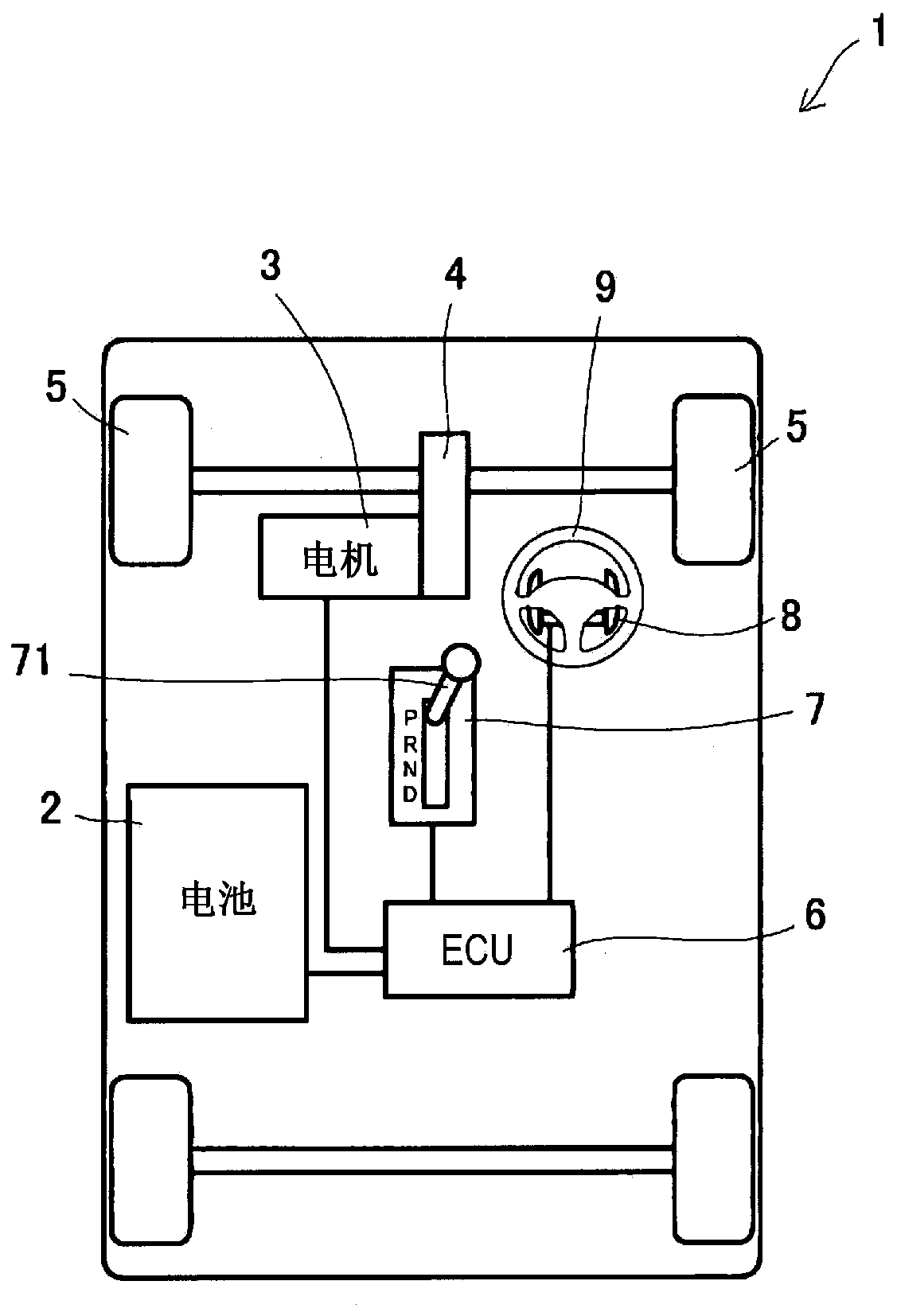
[0020] Such as figure 1 As shown, for example, an electrically driven vehicle 1 is an electric vehicle provided with a battery 2 and a drive motor (rotating motor) 3 . Battery 2 is a rechargeable battery. The driving motor 3 is operated by electric power supplied from the battery 2 . The drive motor 3 is connected to drive wheels (front wheels in the embodiment) 5 through a drive mechanism 4 . Examples of the drive mechanism 4 include CVT (Continuously Variable Transmission), differential gears, and the like. During a so-called regenerative operation, while driving the driving wheels 5 by the driving mechanism 4 , the driving motor 3 receives rotation from the driving wheels 5 to generate electric power and supplies the electric power to the battery 2 . This supply / reception of electric power between the drive motor 3 and the battery 2 is controlled by an ECU (Electronic Control Unit) 6 .
[0021] Incidentally, the ECU 6 is formed as an LSI device integrating a CPU (microp...
Embodiment approach 2
[0045] The present embodiment is an example designed so that when the predetermined regeneration level restricting condition is satisfied, even if the switch lever 81 is operated two or more times within a predetermined time, the stage to which the regeneration level can be limited is changed.
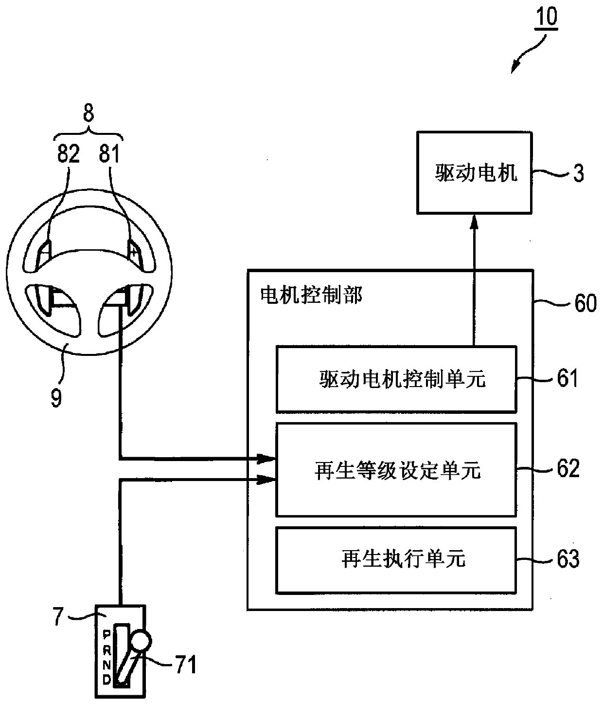
[0046] Such as Figure 5 As shown, the motor control unit 60 constituting the regeneration control device 10 according to Embodiment 2 is provided with a drive motor control unit 61, a regeneration level setting unit 62, and a regeneration execution unit 63, and is also provided with a charge state detection unit 64, a route information detection unit unit 65 and a conditional establishment determination unit 66 .
[0047] The state of charge detection unit 64 detects the state of charge (SOC) of the battery 2 provided in the electrically driven vehicle 1 . For example, charge state detection unit 64 calculates the SOC of battery 2 from an initially stored map (map) based on voltage i...
Embodiment approach 3
[0068] This embodiment is a modification of the second embodiment. Specifically, the present embodiment is an example designed such that when the electrically driven vehicle travels on a curve, it is determined that the regeneration level restriction condition holds.
[0069] Such as Figure 8 As shown, the motor control unit 60 constituting the regeneration control device 10 according to Embodiment 3 is not only provided with a driving motor control unit 61, a regeneration level setting unit 62, a regeneration execution unit 63, and a condition determination unit 66, but also provided with a running state Detection unit 67.
[0070] The running state detection unit 67 detects the running state of the electrically driven vehicle 1 . For example, in the present embodiment, the electrically driven vehicle 1 is provided with various sensors such as a vehicle speed sensor (vehicle speed detection unit) 32 which can be used to detect the vehicle speed and a steering angle sensor ...
PUM
 Abstract
Description
Claims
Application Information
 - R&D
- Intellectual Property
- Life Sciences
- Materials
- Tech Scout
- Unparalleled Data Quality
- Higher Quality Content
- 60% Fewer Hallucinations
Browse by: Latest US Patents, China's latest patents, Technical Efficacy Thesaurus, Application Domain, Technology Topic, Popular Technical Reports.
© 2025 PatSnap. All rights reserved.Legal|Privacy policy|Modern Slavery Act Transparency Statement|Sitemap|About US| Contact US: help@patsnap.com