
Elevator car door motor structure

A technology of door machine and elevator car, which is applied to elevators in buildings, transportation and packaging, etc. It can solve problems such as increased noise in elevator operation, elevator failure, shaking and collision, etc., and achieves noise reduction, convenient use, and reduced shaking effect

Inactive Publication Date: 2017-02-15
SUZHOU HEYANG METAL PROD
View PDF0 Cites 1 Cited by
  • Summary
  • Abstract
  • Description
  • Claims
  • Application Information

AI Technical Summary

Problems solved by technology

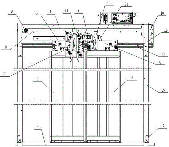
[0003] The existing elevator door machine structure includes a door head, a drive assembly fixed on the door head, a motor, and a hanging plate assembly. The hanging plate assembly is connected with the driving assembly and the motor, and a door knife mechanism is installed on the hanging plate assembly. The movement of the driving component drives the movement of the hanging plate assembly, which drives the door panel to open and close; the left hanging plate and the right hanging plate on the hanging plate assembly are installed on the hanging plate guide rail, and the rollers on the hanging plate are on the hanging plate guide rail However, in the process of use, since the hanging plate and the guide rail are only in contact with the rollers, it is easy to shake and collide, which increases the noise of the elevator operation, and even derails, resulting in elevator failure.

Method used


Image

  • Elevator car door motor structure
  • Elevator car door motor structure
  • Elevator car door motor structure

Examples


Embodiment Construction

[0018] The present invention will be described in detail below in conjunction with the accompanying drawings.

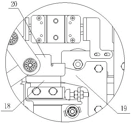
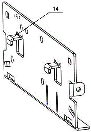
[0019] Such as figure 1 , figure 2 as well as image 3 A door machine structure of an elevator car is shown, comprising a door head 1, a left door panel 2 and a right door panel 3 are arranged below the door head 1, and a door panel guide rail 4 is provided below the door machine for the left door panel 2 and the right door panel 3. The right door panel 3 slides, the left door panel 2 is provided with a left hanging panel 5, the right door panel 3 is provided with a right panel 6, and the left panel 5 is provided with a door knife 7, A driving wheel and a driven wheel 8 are arranged in the door head 1, and a synchronous belt 9 is arranged on the driving wheel and the driven wheel 8. The driving wheel is driven by a driving motor 10, and the left hanging plate 5 is connected to the upper synchronous belt through the left connecting plate 11, the right hanging plat...


PUM


Abstract

The invention relates to an elevator car door motor structure which comprises a door head, wherein a left door plate and a right door plate are arranged below the door head; a door plate guide track used for sliding of the left door plate and the right door plate is arranged below a door motor; a left hanging plate is arranged on the left door plate; a right hanging plate is arranged on the right door plate; a door coupler is arranged on the left hanging plate; a driving wheel and a driven wheel are arranged in the door head; a synchronous belt is arranged on the driving wheel and the driven wheel; the driving wheel is driven by a drive motor; the left hanging plate is connected onto the upper layer of the synchronous belt through a left connecting plate; the right hanging plate is connected onto the lower layer of the synchronous belt through a right connecting plate; a hanging plate guide track is arranged in the door head; the left hanging plate and the right hanging plate are arranged in the hanging plate guide track; guide balls are arranged on both the left hanging plate and the right hanging plate; and clamping plates are arranged on the inner sides of the left hanging plate and the right hanging plate, and clamped on the hanging plate guide track. As the clamping plates are arranged on the hanging plates and clamped on the hanging plate guide track, shaking of the hanging plates during motion and generation of noise can be reduced, smooth running can be guaranteed, and derailment can be avoided; and the elevator car door motor structure is convenient to use.

Description

technical field [0001] The invention relates to the production and manufacturing industry of elevators, in particular to an elevator car door machine structure. Background technique [0002] The elevator door operator is a mechanism responsible for opening and closing the elevator hall car door. When it receives the elevator door opening and closing signal, the elevator door operator controls the door opening motor through its own control system, and converts the torque generated by the motor into a specific direction. force to close or open the door. When the door closing force is greater than 150N, the door operator will automatically stop closing the door, and open the door in reverse, playing a certain degree of door closing protection. [0003] The existing elevator door machine structure includes a door head, a drive assembly fixed on the door head, a motor, and a hanging plate assembly. The hanging plate assembly is connected with the driving assembly and the motor, ...

Claims


Application Information

Patent Timeline
IPC IPC(8): B66B13/30
CPCB66B13/303
Inventor 项新兵何贤超潘薛生
Owner SUZHOU HEYANG METAL PROD
Learn More